1. INTRODUCTION
Active space exploration programs entail overpopulating the most required orbits by artificial objects of various applications (Blake 2022). According to current data, continuously updated public catalogs include over 50,000 artificial space objects with a size of 10 cm and above, of which 5,677 are operational satellites (Lei et al. 2018; Boley & Byers 2021; Shakun et al. 2021). Moreover, according to statistical estimates, the total number of functional and non-functional space objects with a diameter of approximately 1 cm in low Earth orbit has already reached one million. Commensurate with the growth in the number of orbital missions, there is a need to scale up existing space surveillance networks, both radio and optical (Kyono et al. 2020; Pastor et al. 2021; Spiridonov et al. 2021). Additional information sources on the space situation using passive optical systems with small aperture telescopes (less than 50 cm) (Chun et al. 2015; Guo et al. 2020; Danescu et al. 2022) are actively developing and contributing to resolving the problem of congestion in global networks within the scope of regional and national monitoring (Yanagisawa et al. 2015; Park et al. 2018; Lei et al. 2021).
Space object detection using optical measurement data is equivalent to the classical problem of detecting a signal in the realization of a stochastic process against an unknown noise (Stark 1982). The unknown noise is caused by the effects of star twinkling, dynamic light pollution, and atmospheric turbulence instability (Hickson 2018; Azimov et al. 2022). In general, even the optical signal, representing the reflected light from a space object, is not deterministic. It is necessary to consider that the optical signal from a space object can arise as a random process realization to develop a robust detection method. The uncertainty relates to the intensity modulations due to the heterogeneity of the optical flux reflection from the space object surface during its orbital rotation (Krantz et al. 2023). In addition, the uncertainty of the optical signal appears at the moment of the orbit correction, when the space object is moved in some direction relative to an unknown observer. Therefore, it is not enough to analyze individual realizations to determine optimally whether a signal is present in the measured data (Oniga et al. 2011; Torteeka et al. 2019; Cooke et al. 2023).
Depending on the optical measurement technology, the space object intensity signal can be presented as an elongated track against a background of stationary stars or an elliptical spot against a background of star tracks (Hwang et al. 2019; Suthakar et al. 2023). As an evolving concept in existing detection methods that have found practical applications, the convolution of the single-measurement intensity signal or sequence of optical measurements with a morphological filter is used (Sun et al. 2015; Chote et al. 2019; Cooke et al. 2023). Based on the known waveform, a suitable morphological filter is developed, which detects the maximum correlation when the filter matches the form of the space object intensity (Lévesque 2009). Variations in the shape of the morphological filter are limited to the synthetic generation of the line, whose length matches the estimated size of the space object track. In Hickson (2018), the track length assumptions are based on the exposure time and the approximate space object velocity. Another approach to filter development is to generate a line using the coordinates of two points. Point coordinates are calculated using a prediction model based on known space object orbital parameters (Blake et al. 2021). The above approaches use the ideal line of different lengths and orientations as the reference. It is assumed that the space object track in the intensity signal realization will be unambiguously defined. For the waveform to be unambiguously determined, the global threshold technology, which removes low-frequency noise and binarizes the image, is pre-applied (Diprima et al. 2018; Wijnen et al. 2019; Dokkum & Pasha 2024). An evident problem in this case is the uncertainty in the intensity threshold value, which requires an adaptive estimation of the signal-to-noise ratio for each measurement. Convolution with such a morphological filter encounters the problem of ambiguity, where the track length varies depending on the intensity modulation, observation conditions, and the accuracy of the apriori known orbital parameters. In addition, the full-scale image of the filter is a costly computing process.
An alternative to the classical method of optical measurements and the approach to implementing a matched filter can be the use of video data and features of the difference frame sequence of this data (Baranova et al. 2021, 2023). Encoding the optical measurement video stream into a single source file as multiple realizations of a random process allows for accumulating sufficient information for summation and subtraction operations with minimal noise levels in each realization. This representation method depicts a space object as a local area of pixels with varying intensities. The magnitude of displacement within this area depends on the space object velocity, which is accurately determined by its orbital parameters. This implies that there is a functional dependence between the motion dynamics of the object in the frame plane and its orbital parameters. Such functional dependence can be used to extract stable features and build a set of filters in the frequency domain to solve the problem of detecting resident space objects (RSO) using an optical observation system (Spiridonov et al. 2022).
The main goal of developing and researching such a detection method is the endeavor to remove the limitation from methods solving the problem of initial orbit determination based on angular data, where there is no information about the range to the RSO. It is known that the slant range is a key parameter for determining the space object’s orbit. Therefore, in the proposed study, the detection method differs in that it includes a consistent estimation of the linear velocity projection onto the frame plane, enabling the estimation of the slant range. Range information allows for calculating the position vector of the RSO at each measurement point without iterative approximation, which enhances efficiency and simplifies the initial orbit determination. The proposed detection method is autonomous and involves processing a video stream using a set of matched filters based on the connection between the Fourier spectrum shape of the difference frame and the magnitude of the linear velocity projection onto the observation plane.
2. MATCHED-FILTERING TECHNIQUE FOR THE SPACE OBJECTS DETECTION
The random intensity of the reflected optical flux from the surface space object makes it impossible to establish apriori values of this parameter as a detection threshold. The basis for feature extraction should be the texture or, in other words, the waveform. More than a single realization of a random process or a single frame is required to determine the presence or absence of a signal, especially when considering a space object as a local pixel region that resembles stars in terms of texture. Therefore, using not just one but multiple frames of the video stream makes sense. The apparent characteristic of a space object in a video sequence is motion. It is necessary to use a difference frame to represent the motion of an object as a distinct texture (Baranova et al. 2023). The formation of a difference frame is determined by the characteristics of observed space objects: their brightness and velocity. The term RSO will be used further, implying the ability to apply the detection model to both artificial and natural space objects, such as satellites, debris, and asteroids (Wlodarczyk et al. 2017; Alton & Stępień 2019).
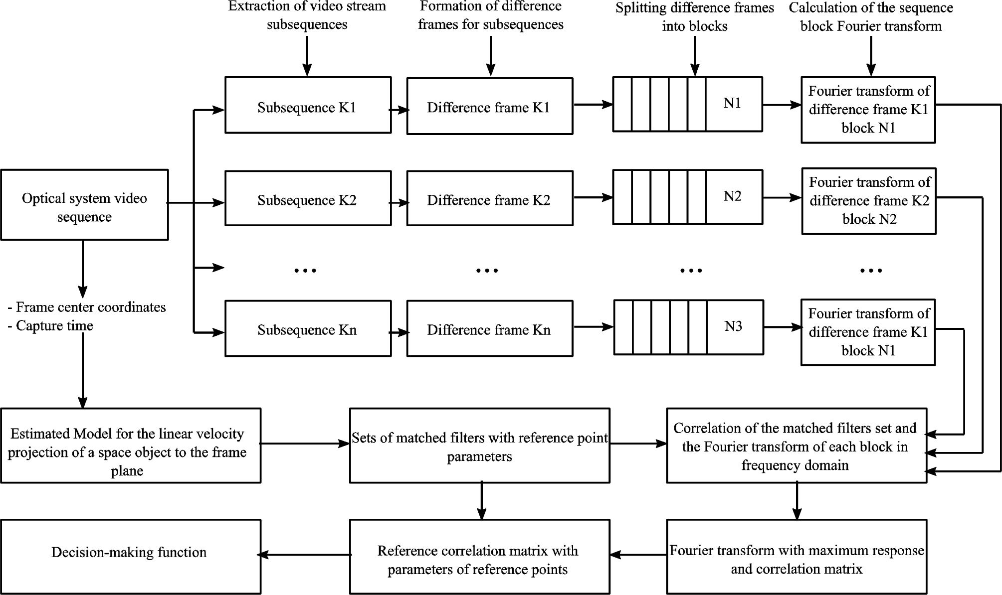
The Fourier spectrum shape of the difference frame with the intensity signal of the RSO at a given moment in time is closely related to the parameters of its orbital motion. Therefore, given the Fourier spectra of a known RSO with the corresponding angular coordinates and observation time, it is possible to create a matched filter for detecting another RSO with known or unknown orbital parameters. For this purpose, the dependence of the linear velocity projection onto the frame plane and the declination value within the pass observation interval is calculated. Then, reference points with angular coordinates where the Fourier spectrum of the RSO is known on the curve are determined. Based on the known Fourier spectrum, a matched filter is constructed. The matched filter represents a mask with linear velocity projection and angular coordinate parameters. Sets of matched filters are stored in the local database of the optical observation system as additional data for the catalog of RSO orbital parameters. The flowchart of the detection algorithm is presented in Fig. 1. First, the input video sequence with a total number of frames N is divided into subsequences, where the number of frames in each subsequence is k. For each subsequence, a difference frame is generated according to the strategy of subtracting the accumulated sums of n frames. The difference frames of these subsequences are divided into blocks of size 64 × 64. Then, the Fourier transform is calculated for each block of the difference frame. The obtained Fourier transforms of the input video stream are passed to a part of the processing algorithm, where correlation values between these Fourier transforms and reference masks are calculated in the frequency domain. The correlation of a two-dimensional function f (x, y) of each Fourier transform with a reference mask h (x, y) is determined by the expression:
where (x, y) are the spatial variables, in the context of an image, these are the pixel coordinates, m × n is the reference mask size, a and b are non-negative numbers defined as a =(m – 1) /2, b = (n – 1) / 2, s and t represent the coordinates of the reference mask coefficients and the offset variables for the two-dimensional function f (x, y).
According to the two-dimensional convolution theorem (Gonzalez & Woods 2006), the inverse discrete Fourier transform of the product of the input signal Fourier transform F (u, v) and the reference mask Fourier transform H (u, v) is equivalent to a two-dimensional convolution f (x, y) and h (x, y) in the spatial domain. The product operation is known to be computationally more efficient than correlation. Therefore, in the detection task, the matched filtering algorithm uses the spectra of the difference frame F (u, v) and reference masks H (u, v). For each sequence of difference frames, correlation with a set of matched filters or masks is determined according to the two-dimensional convolution theorem:
where F*(u,v) is complex conjugation of the input signal intensity and a two-way arrow ⇔ indicates that the expressions on the right and left sides Eq. (2) form a Fourier pair (Gonzalez & Woods 2006).
The central equation of matched filtering in the frequency domain, which is used to calculate the correlation pattern g(x,y) in the spatial domain:
where ϑ–1 is the inverse Fourier transform operator.
In a more accurate form, the equation of the correlation pattern in the spatial domain is written, taking into account that the Fourier transform of the difference frame and the reference mask are complex arrays:
where Fr(u,v), Fi(u,v) are real and imaginary parts of the difference frame transform, Hr(u,v), Hi(u,v) are real and imaginary parts of the reference mask transform.
The correlation pattern g(x,y) of difference frame discrete blocks F(u,v) and the reference mask H(u,v) in the detecting RSO algorithm is represented as follows:
where multiplying by (–1)x+y is used to center the Fourier transform (Gonzalez & Woods 2006), the abs operator denotes (determines) the magnitude of the correlation value for each point g(x,y).
3. ESTIMATED MODEL FOR THE RESIDENT SPACE OBJECTS (RSO) LINEAR VELOCITY PROJECTION TO THE FRAME PLANE
The estimation model for reference points matched with the known RSO Fourier transform F(u,v) is based on calculating the linear velocity projection onto the frame plane Vplane as a function of the angular coordinates of declination δ. The idea is that for each moment where the projections of the RSO linear velocity are the same, the correlation between the spectra of their difference frames will be close to or equal to unity in the case of normalized data. Therefore, the matched filter represents the Fourier spectrum of the known RSO difference frame at a certain point with known values of linear velocity projection and angular coordinates. Such a matched filter will detect the presence of an unknown RSO in the frame plane at points with velocities closest to the reference object.
The dependence of the linear velocity projection Vplane onto the frame plane as a function of declination δ is calculated as follows. The topocentric coordinate system associated with the frame plane is presented in Fig. 2. Based on the known RSO’s state vector, which includes the position vector r(X,Y,Z) and the velocity vector v(VX,VY,VZ) in the Earth-Centered Inertial (ECI) coordinate system OXYZ, for each point of the pass interval at which the measurements were taken, the slant range vector and its rate of change in the topocentric equatorial coordinate system O1X1Y1Z1 associated with the observation point O1 are given by:
where is slant range vector projections onto the coordinate axes of the topocentric equatorial coordinate system (Vallado & McClain 2013), θLST is the local sidereal time of the observation point, is the radius of Earth’s curvature in the meridian, eE = 0.081 819 221 456 is the Earth eccentricity, RE = 6,378.135 km is the Earth radius, rδ = (CE + H)cosφos is the radius vector projection of the observation point onto the equatorial plane, φos is the observation point geodetic latitude, rK = (SE + H)sinφos is the radius vector projection of the observation point onto a plane perpendicular to the equatorial plane, is Earth curvature parameter, H is the observation point height above the Earth ellipsoid, r is the RSO position radius vector in the ECI coordinate system, ros is the position radius vector in the observation point relative to the Earth center, V is the RSO velocity vector in the ECI coordinate system, ωE = (0, 0, ωE) is Earth rotation angular velocity (angular velocity module ωE = 7.292 115 146 7·10-5 rad/s).
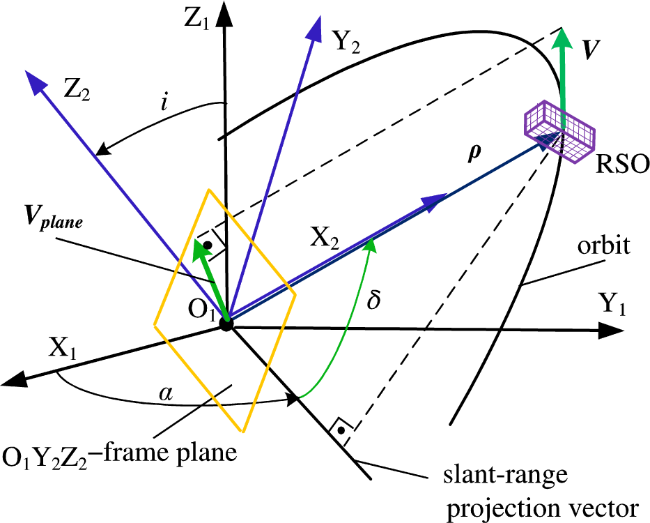
Topocentric declination δ and right ascension α, which characterize the RSO position at the moment t relative to the observation point, are calculated as follows:
Then, the coordinates and projections of the RSO velocity are determined in a topocentric coordinate system O1X2Y2Z2 associated with the frame plane – the O1X2 axis is directed perpendicular to the frame plane, and the O1Y2 and O1Z2 axes lie in the frame plane (Fig. 2).
The RSO slant range vector and its rate of change in the topocentric coordinate system O1X2Y2Z2 associated with the frame plane could be written as:
where i is the inclination that refers to the tilt of the RSO’s orbit plane.
Rotation matrices that rotate a vector around the O1X1 and O1Z1 axes are given by:
Then the projection of the RSO linear velocity Vplane onto the frame plane at time t is determined by the following formula:
If an estimate of the RSO linear velocity Vplane at time t is obtained, then it is also possible to find the initial approximation of the slant range vector and, consequently, the position vector r(X,Y,Z) in the ECI coordinate system. The geometric representation of the approach to calculating the initial approximation of the slant range vector based on the linear velocity Vplane is shown in Fig. 3. The first step involves using the results of RSO detection by the proposed method of matched filtering to determine topocentric declination δ and right ascension α at time moments t и t+Δt. The second step is to form slant range unit vectors L:
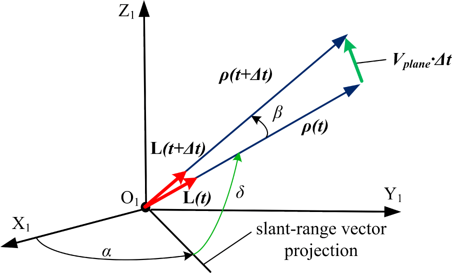
Then angle β between slant range vectors at time moments t и t+Δt is calculated:
Finally, estimation of slant range vectors and the position vector r(X,Y,Z), which is expressed by Eq. (6), in the ECI coordinate system at time moment t are determined:
4. RESULTS
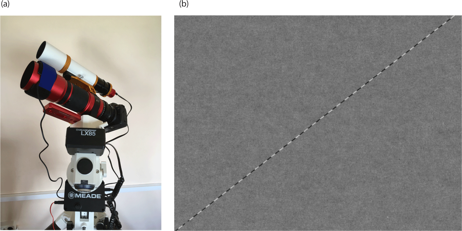
The possibility of RSO detection in video data using the matched filtering method was investigated. Experimental data were obtained by the mobile optical surveillance system for low-orbit space objects at the Belarusian State University (Spiridonov et al. 2022; Baranova et al. 2023). The optical system with an effective field of view 8°14’’ based on the wide-angle apochromatic lens RedCat 51 APO with a focal length of 250 mm and the f-number 4.9 is mounted on a computerized rotator with the maximum slew rate of 4 deg/sec. The sensor is a full-format Canon EOS R camera with a video data transfer rate of up to 480 Mbps via the HDMI port. The frame size is in pixels 1920 × 1080 with an .avi encoding format. The optical surveillance system for low-orbit space objects provides orbit angular measurements of operational satellites and space debris objects up to 9th magnitude. The mobile optical system is shown in Fig. 4(a). An example of a 10 s video sequence difference frame with the AQUA satellite intensity signal is shown in Fig. 4(b).
Difference frames of video data with the AQUA (NORAD: 27424) satellite pass were used to construct a matched filter at three capture intervals in a region with known angular coordinates. Preliminary results from processing experimental videos with intensity signals from various satellites have shown that the Fourier spectra of the differential frames obtained by subtracting the accumulated sums of every three frames exhibit the highest uniformity and stable signal-to-noise ratio. Therefore, in most experiments, a difference frame calculated according to the following formula was used as the basis for the intensity signal characterizing the dynamics of the RSO motion:
where Δf(x,y,tk) is k-th difference frame of the video sequence, Δf(x,y,tk–1) is previous difference frame of the video sequence, f(x,y,ti) is i-th frame of the video sequence, n = 2 is number of frames for accumulating the sum, t is the time variable.
The detection problem was solved for raw video data with intensity signals of three satellites taken from a series of observations for 05.08.2022–06.08.2022: KORONAS-FOTON (NORAD:33504), CUSAT 2/FALCON 9 (NORAD:39271), GENESIS 1 (NORAD:29252). The orbital parameters of these satellites and the reference satellite AQUA are presented in Table 1. Here, rp and ra are perigee and apogee radius, i is orbit inclination, and T indicates the orbit period.
The functional dependence of the RSO linear velocity projection Vplane onto the frame plane from the declination δ for each satellite under consideration concerning the dependence of the reference satellite AQUA δr was calculated. As a result of the matched filtering algorithm, the satellites KORONAS-FOTON, CUSAT 2/FALCON 9, and GENESIS 1 were automatically detected in a sequence of difference frame blocks in the region with the following angular coordinates: KORONAS-FOTON–α1 = 18h14m17s, δ1 = 31°01′52″; CUSAT 2/FALCON 9–α3 = 16h24m51s, δ3 = 72°18′56″; GENESIS–α2 = 05h18m56s, δ2 =71°40′42″.
According to the functional dependence obtained from the linear velocity projection onto the frame plane from the declination, space objects were detected at the corresponding points using masks containing the AQUA satellite’s intensity signal with linear velocity projection values close to the detected objects. The calculated curves of the linear velocity projection onto the frame plane from the declination with marked points at which objects were detected are shown in Fig. 5. Additionally, points of the curve for the reference object are marked, where the generated masks identified a correlation pattern with the maximum coefficient values.
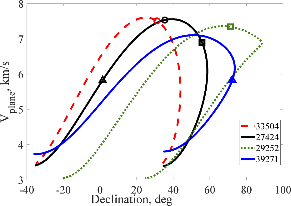
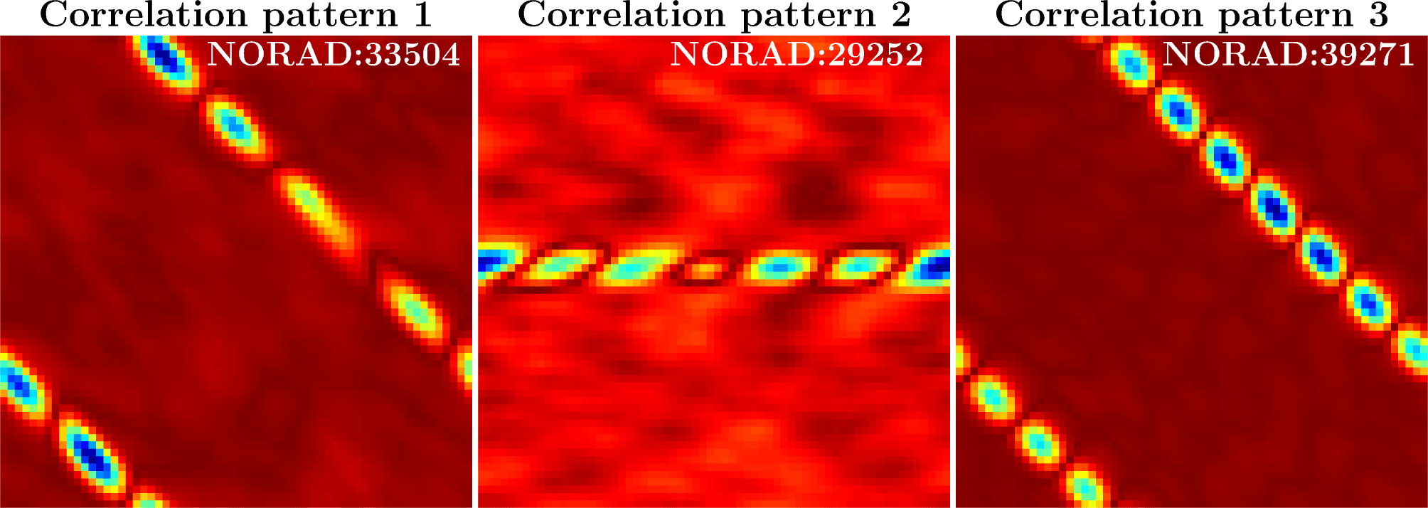
In the Fig. 5 reference and detected objects, curve points are identically marked on the curve: AQUA and KORONAS-FOTON points are red and black circles, for AQUA and GENESIS points are marked by black and green squares, AQUA and CUSAT 2/FALCON 9 points are black and blue triangles. The resulting correlation patterns for each pair of points of the reference mask and the detected satellite, in particular, AQUA and KORONAS-FOTON (correlation pattern 1), AQUA and GENESIS (correlation pattern 2), AQUA and CUSAT 2/FALCON 9 (correlation pattern 3) are presented in Fig. 6, respectively.
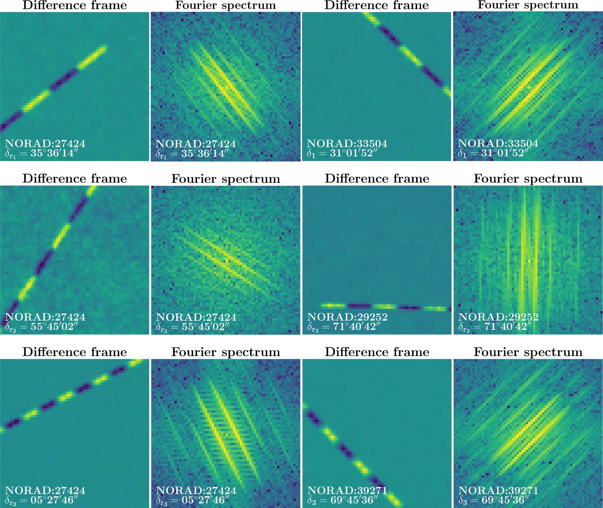
The reconstructed areas of difference frames with the intensity signal of the detected satellites, masks of the AQUA satellite at reference points, and their Fourier images are shown in Fig. 7.
Analyzing the obtained results, it can be concluded that the closer the values of the linear velocity projection onto the frame plane of the reference mask and the detected satellite, the higher the maximum correlation value and the symmetry of the correlation patterns. For the CUSAT 2/FALCON 9 satellite, the curve of the linear velocity projection Vplane from the declination δ (Fig. 5, blue line with triangle marker) reflects the minimum difference between the value Vplane at declination δ3 = 72°18′56″ and the value Vplane of the generated mask with AQUA satellite (Fig. 5, black line with triangle marker) at declination is equal to ΔVplane3 = 0.0079 km/s. The correlation image of the reference satellite AQUA and the detected satellite CUSAT 2/FALCON 9 is presented in Fig. 6 (correlation pattern 3).
Notably, the correlation pattern for this satellite contains an additional component that corresponds to the frequency component of the Fourier image of the differential frame. This is caused by the inhomogeneity of the intensity signal of both the satellite itself and the reference object mask. This effect is observed in the Fourier images of difference frames in Fig. 7 for the CUSAT 2/FALCON 9 satellite and the reference mask with the AQUA satellite. As is the case for the detected satellite KORONAS-FOTON.
For the KORONAS-FOTON satellite, the correlation pattern of which is shown in Fig. 6 (correlation pattern 1), the curve of the linear velocity projection Vplane from the declination δ (Fig. 5, red line with circle marker) shows the difference of Vplane in the point region δ1 = 31°01′52″ and the value of Vplane in the declination region of the generated AQUA satellite mask (Fig. 5, black line with circle marker) is equal to ΔVplane1 = 0.0263 km/s. Accordingly, for the detected GENESIS satellite, the difference between the projection of linear velocity Vplane at declination δ2 = 71°40′42″ (Fig. 5, green line with square marker) and the value Vplane of the generated mask with AQUA satellite (Fig. 5, black line with square marker) at declination is ΔVplane2 = 0.4387 km/s. The correlation pattern of AQUA and GENESIS is presented in Fig. 6 (correlation pattern 2).
It is worth noting that the difference in the inclination angle of the Fourier image of the reconstructed intensity signal of the detected satellites and the reference satellite mask with preliminary mirror operation corresponds to the difference in the orbit inclinations of these objects (Fig. 7). This is confirmed by the obtained mask rotation angle values for the maximum correlation value with detected objects: Δφ1 = 16° for AQUA and KORONAS-FOTON, Δφ2 = 34° for AQUA and GENESIS, as well as Δφ3 = 17° for AQUA and CUSAT 2/FALCON 9. The established dependence will be investigated in further work.
By calculating the linear velocity projection Vplane for each satellite, the initial approximation of the slant range vector was found. The results of RSO detection by the proposed method to calculate topocentric declination δ and right ascension α at time moment’s t и t + Δt = t + 5 s were used. Estimation of slant range vectors at time moment t were determined: (28.2 km, –743.4 km, 439.1 km) for KORONAS-FOTON with an absolute error for slant range module 2.5 km (relative error 0.3%) relative to the slant range module obtained in the SGP model using the initial orbital data in TLE format; (–27.6 km, –354.8 km, 480.7 km) for GENESIS with an absolute error 33.5 km (relative error 5.3%); (–125.3 km, –332.9 km, 1,120.4 km) for CUSAT 2/FALCON 9 with an absolute error 8.1 km (relative error 0.7%).
Also the initial approximations of the position vector r(X,Y,Z) in the ECI coordinate system were calculated: (3,704.2 km, –1,643.9 km, 5,556.0 km) for KORONAS-FOTON with an absolute error for position vector module 2.6 km (relative error 0.04%) relative to the position vector module obtained in the SGP model using the initial orbital data in TLE format; (2,782.2 km, –2,890.4 km, 5,597.6km) for GENESIS with an absolute error 27.1 km (relative error 0.4%); (2,346.8 km, –3,198.0 km, 6,237.3 km) for CUSAT 2/FALCON 9 with an absolute error 9.0 km (relative error 0.1%).
Despite the fact that the error in determining the linear velocity Vplane was minimal for the CUSAT 2/FALCON 9 (ΔVplane3 = 0.0079 km/s), the absolute error in determining the slant range and position vector module turned out to be higher (8.1 km and 9.0 km, respectively) than that of the KORONAS-FOTON. This is due to the ellipticity of the CUSAT 2/FALCON 9 orbit (e = 0.0519) compared to the reference satellite AQUA (e = 0.0002), which has an orbit close to circular. On the contrary, the KORONAS-FOTON (e = 0.0020) achieves the most precise result in determining the slant range and position vector module (absolute errors are 2.5 km and 2.6 km, respectively) due to its nearly circular orbit, despite having a less accurate determination of the linear velocity projection (ΔVplane1 = 0.0263 km/s) compared to CUSAT 2/FALCON 9. The GENESIS (e = 0.0057) exhibited the highest absolute error in the value of the slant range vector and position vector module (33.5 km and 27.1 km, respectively), attributed to the greatest error in determining the linear velocity projection (ΔVplane2 = 0.4387 km/s) during the detection stage. The accuracy of predicting the linear velocity projection of the detected satellite is determined by the proximity of this value to the linear velocity projection of the matched filter that provided the highest response. It is worth noting that the parameters of the matched filter are the known motion parameters of the reference satellite in a specific area of the sky. The more measurement data available at different points on which matched filters are constructed, the more accurately the linear velocity projection of the unknown object can be determined.
According to the obtained results, optical measurements can be reduced to the task of preliminary determination of features related to the parameters of the RSO’s orbits, which was the goal of this research. It is evident that the direct detection and estimation of such a key parameter as slant range are combined through a matched filtering approach. To maximize the signal-to-noise ratio at each spatial point of the image, a special texture of the difference frames from accumulated sums was used. At this stage of the research, the filter included an estimation of the linear velocity projection of the space object onto the frame plane, the value of which provides an approximation of the slant range. Additionally, during the research, the possibility of estimating the orbit inclination was ident ified, which expands the output of the matched filter by directly determining one of the six orbit parameters. Furthermore, in Baranova et al. (2024) the authors conducted a geometric approach to determining the orbit altitude based only on angular measurements. This approach will complement the presented method of matched filtering with information about the altitude of the space object’s orbit.
A comprehensive algorithm for initial orbit determination based on the initial estimation of the above-mentioned parameters is beyond the scope of this work. Ultimately, the information on angular coordinates, time, linear velocity projection onto the frame plane, slant range, inclination, and orbit altitude combined with the texture of the differential frame and its Fourier transform of a specific space object leads the subject of future research towards accumulating a greater quantity of annotated optical measurement data. Sufficient data volume will enable the creation of models for real-time detection and orbit determination of space objects based on visual observations using deep learning algorithms.
5. CONCLUSION
A method for detecting RSOs in video data using a set of matched filters was proposed. Matched filters are constructed based on the connection between the Fourier spectrum shape of the difference frame and the magnitude of the linear velocity projection onto the observation plane. The research was carried out as part of the stable detection system development for the mobile optical surveillance station of low-orbit space objects at the Belarusian State University.
To construct a matched filter, difference frames of video data with the AQUA satellite pass were used at three capture intervals in a region with known angular coordinates. The detection problem was solved for raw video data with intensity signals from three satellites: KORONAS-FOTON, CUSAT 2/FALCON 9, and GENESIS 1. As a result of the matched filtering algorithm, the satellites KORONAS-FOTON, CUSAT 2/FALCON 9, GENESIS 1 were automatically detected in a sequence of difference frame blocks in the region with the following angular coordinates: KORONAS-FOTON–α1 = 18h14m17s, δ1 =31°01′52″; CUSAT 2/FALCON 9–α3 = 16h24m51s, δ3 =72°18′56″; GENESIS–α2 = 05h18m56s, δ2 =71°40′42″.
The functional dependence of the RSO linear velocity projection Vplane onto the frame plane from the declination δ was calculated for each satellite under consideration with the dependence of the reference satellite AQUA. Correlation patterns were obtained for each point pair of the reference mask and the detected satellite, specifically, AQUA and KORONAS-FOTON, AQUA and GENESIS, and AQUA and CUSAT 2/FALCON 9. The satellites were detected at points where the difference in the value of their linear velocity projection and the reference satellite was: AQUA and KORONAS-FOTON ΔVplane1 = 0.0263 km/s, AQUA and GENESIS ΔVplane2 = 0.4387 km/s, AQUA and CUSAT 2/FALCON 9 ΔVplane3 = 0.0079 km/s.
The estimated model for the RSO linear velocity projection allows obtaining an initial approximation for the slant range vector and the position radius-vector of the satellite at time t, when an estimate of the projection of the velocity vector was obtained. A comparison of the results of determining these vectors with the simulation data in the SGP model was carried out based on the initial orbital data in the TLE format of the NORAD system. Absolute errors in an initial approximation for the slant range vector of the KORONAS-FOTON, GENESIS and CUSAT 2/FALCON 9 are 2.4 km, 33.5 km, 8.1 km, respectively. Additionally, the absolute errors of the position radius-vector for the corresponding satellites are 2.6 km, 9.0 km, and 27.1 km, respectively. The accuracy of the results depends on the magnitude of the error in determining the projection of the velocity vector and the elevation angle of the satellite above the observation point.
It has been established that the difference in the inclination angle of the Fourier image of the reconstructed intensity signal of the detected satellites and the reference satellite mask with preliminary mirror operation corresponds to the difference in the orbit inclinations of these objects. This is confirmed by the obtained mask rotation angle values for the maximum correlation value with detected objects: Δφ1 = 16° for AQUA and KORONAS-FOTON, Δφ2 = 34° for AQUA and GENESIS, as well as Δφ3 = 17° for AQUA and CUSAT 2/FALCON 9.
The proposed method allows for detecting and studying RSOs’ motion parameters. In particular, the Fourier image of the difference frame approximates the velocity, the angular coordinate of declination, and the satellite orbit inclination relative to the reference space object. The value of the velocity provides an estimate of the slant range, which simplifies one of the most complex computational steps of any initial orbit determination method based only on angular measurements. The identified correlations provide an approximation of the inclination and orbit altitude of the unknown space object. However, it is worth noting that at the moment, the proposed method is limited by a small amount of reference data. The probability of detection is related to the proximity of the velocities of the unknown and reference space objects. The parameters of experimental optical measurements of the reference space object orbit are the parameters of the matched filter. Therefore, the more measurements of various types of RSO orbits are used to construct filters, the greater the response and consequently, the more accurately the velocity value can be estimated. An alternative to using a significant number of coordinated filters is the construction of extended filters for specific classes of orbits. The proposed method is planned to be further developed into a coherent detection method with real-time estimation of the unknown RSOs orbits, including space debris objects after fragmentation or collision.


