Research Paper

Perturbations of Zonal and Tesseral Harmonics on Frozen Orbits of Charged Satellites

Fawzy Ahmed Abd El-Salam1,2https://orcid.org/0000-0002-4107-9347, Walid Ali Rahoma1,3,https://orcid.org/0000-0002-3529-2731, Magdy Ibrahim El-Saftawy4https://orcid.org/0000-0002-1974-6676, Ahmed Mostafa5https://orcid.org/0000-0003-1267-6182, Elamira Hend Khattab1,3https://orcid.org/0000-0001-5109-7410
Author Information & Copyright
1Department of Astronomy, Faculty of Science, Cairo University, Cairo 12613, Egypt
2Department of Mathematics, Faculty of Science, Taibah University, Al-Madinah 41477, Saudi Arabia
3Applied Mathematics Department, Misr International University, Cairo 11828, Egypt
4Department of Space Science and Astronomy, Faculty of Science, King Abdulaziz University, Jeddah 21589, Saudi Arabia
5Department of Mathematics, Faculty of Science, Ain Shams University, Cairo 11566, Egypt
Corresponding Author : Tel: +20-1001084906, E-mail: walid.rahoma@cu.edu.eg

© Copyright 2024 The Korean Space Science Society. This is an Open-Access article distributed under the terms of the Creative Commons Attribution Non-Commercial License (http://creativecommons.org/licenses/by-nc/4.0/) which permits unrestricted non-commercial use, distribution, and reproduction in any medium, provided the original work is properly cited.

Received: Dec 23, 2023; Revised: Mar 20, 2024; Accepted: Mar 25, 2024

Published Online: Jun 30, 2024

Abstract

The objective of this research is to address the issue of frozen orbits in charged satellites by incorporating geopotential zonal harmonics up to J6 and the initial tesseral harmonics. The employed model starts from the first normalized Hamiltonian to calculate specific sets of long-term frozen orbits for charged satellites. To explore the frozen orbits acquired, a MATHEMATICA CODE is developed. The investigation encompasses extensive variations in orbit altitudes by employing the orbital inclination and argument of periapsis as freezing parameters. The determined ranges ensuring frozen orbits are derived from the generated figures. Three-dimensional presentations illustrating the freezing inclination in relation to eccentricity, argument of periapsis, and semi-major axis parameters are presented. Additional three-dimensional representations of the phase space for the eccentricity vector and its projection onto the nonsingular plane are examined. In all investigated scenarios, the impacts of electromagnetic (EM) field perturbations on the freezing parameters of a charged satellite are demonstrated.

Keywords: perturbations in zonal harmonics; electromagnetic perturbations; charged satellites; frozen orbits

1. INTRODUCTION

Frozen orbits are characterized by nearly constant orbital eccentricity (e) and periapsis argument (ω), as discussed by Parke et al. (1987). These orbits are achieved through careful minimization of the drift rates associated with these orbital elements, resulting in an invariant geometric configuration and fixed spatial locations. Consequently, the line of apsides remains a constant vector in the geocentric frame of reference. Examples of commonly used frozen orbits for remote sensing and communication purposes include GEOSAT, LANDSAT, and Molniya.

Tzirti et al. (2009), Carvalho et al. (2010) and Khattab et al. (2020) have conducted analyses on frozen lunar artificial satellites, considering various perturbing models. Tzirti et al. (2010), along with Lara et al. (2010a, b), have explored frozen orbits around Mercury using Lie-Deprit transforms. Delsate et al. (2010), employing a Hamiltonian formalism, determined stable and unstable Mercurian frozen orbits locations. Liu et al. (2010, 2011) have investigated Martian frozen orbits and critical inclination orbits. Rahoma et al. (2014) addressed the critical inclination problem within the Hamiltonian framework, incorporating relativistic corrections and the first sectorial harmonics for an Earth-like planet. Additionally, Rahoma & Abd El-Salam (2014) examined the impact of oblateness and the first sectorial and tesseral harmonics coefficients on a lunar artificial satellite’s critical inclination.

Frozen orbits topic related to uncharged satellites has been extensively studied, Lanchares et al. (2011) conducted an analytical examination of frozen orbit families concerning a prolate celestial body. Abd El-Salam & Abd El-Bar (2016) and Abd El-Salam et al. (2018) investigated specific frozen orbit families for lunar artificial satellites using a singly averaged Hamiltonian considering the oblate and triaxial Moon. Masoud et al. (2018) studied the artificial frozen orbit problem around Earth. Ultimately, the application of frozen orbit concepts may be employed in the orbital design for specific missions within the context of the three-body problem, as highlighted by Zotos (2015).

The prolem’s history extended to include orbits undergoing resonant capture, as demonstrated by Quinn et al. (1995), and Haberman et al. (1999) and the influences of zonal harmonic, sectorial harmonic, and the Earth acting as a third-body perturber, Nie & Gurfil (2018).

Oliveira et al. (2019) investigated the perturbing effects of the Sun on the orbital evolution of artificial satellites following frozen orbits around Mars. A mapping of an irregular asteroid, 216 Kleopatra, research was carried out by Circi et al. (2019), who looked at ground track characteristics related to a frozen orbit.

A frozen orbit maintenance technique for small body exploration was presented by Li et al. (2019). The viability of station-keeping for spacecraft in near-polar and extremely low-altitude quasi-frozen orbits around the Moon was discussed by Singh et al. (2020).

Moreover, the electromagnetic (EM) force, accelerating the charged particle moving in relation to the geomagnetic field, acts perpendicular to its velocity and the magnetic field referred as Lorentz force, see Streetman & Peck (2007a, b) for comprehensive studies. The perturbation induced by EM forces on a charged satellite encompasses several noteworthy properties that significantly influence its orbital dynamics. Firstly, the strength of the EM force acting on the satellite is directly proportional to the product of its charge and the strength of the magnetic or electric field in its vicinity. This implies that a higher charge or a more intense EM field will result in a more pronounced perturbation. Additionally, the direction of the force depends on the relative orientation of the satellite’s charge and the magnetic or electric field vector, contributing to alterations in its trajectory. The perturbation is also influenced by the satellite’s velocity, with greater velocities leading to increased effects due to the interaction between the charged satellite and the surrounding EM fields. Managing and mitigating these perturbations is crucial for accurate satellite positioning and navigation in space missions, highlighting the importance of understanding the intricate properties of EM force-induced perturbations.

The dynamics of electrically charged satellites have been addressed employing Lagrange’s planetary equations by several authors, as Sehnal (1969), Peck (2005), Abdel‐Aziz (2007), Atchison & Peck (2009), Streetman & Peck (2009), Abdel-Aziz & Khalil (2014), Li (2016), Abd El-Salam et al. (2017), Abd El-Bar & Abd El-Salam (2018), Tealib et al. (2020). Using Lie series based on Kamel technique, Kamel (1970), the problem is treated differently and canonically.

This study concerns with the charged satellite’s frozen orbits computations. Our approach considers the oblate geopotential up j6 zonal harmonics enhanced by the first tesseral harmonics.

After this introduction, the single average Hamiltonian is presented in section 2 whereas, the frozen line of apses is addressed in section 3. In section 4, and its subsections, different investigated orbits of the solution of the equation frozen line of apses for the inclination as a freezing parameter for different cases are simulated and discussed. In section 5, the frozen apsidal line equation is solved for the argument of periapsis. In section 6, and its subsections, plotting and analysis are done on several examined orbits of the frozen line of apses solution for the periapsis argument freezing parameter for various circumstances. The freezing eccentricity is calculated in section 7. Section 8 presents the solution to the inclination frozen equation. Three-dimensional graphical representations of the frozen eccentricity are displayed in section 9. The phase space of the eccentricity vector is covered in section 10. Plots of the eccentricity vector’s 2D and 3D phase space portraits are shown in section 11. Section 12 concludes with some last thoughts and recommendations for further research.

2. SINGLY AVERAGED HAMILTONIAN

Recall the six orbital elements (a, e, I, ω, Ω, f), namely the semimajor axis, the eccentricity, the inclination, the argument of periapsis, the longitude of the ascending node and the true anomaly respectively, and the satellite’s longitude of the ascending node (ω) occurs inextricably linked the Earth’s celestial longitude in the frame rotating with the Earth, then the Delaunay variables (l, g, h, L, G, H) can be read as; Delhaise & Morbidelli (1993) and Rahoma (2014, 2016):

l = M , g = ω , h = Ω ω t , L = μ a , G = μ a ( 1 e 2 ) , H = μ a ( 1 e 2 ) cos I
(1)

where M is referes to mean anomaly and t refers to the time.

Employing the normalization perturbed Keplerian systems technique by Ahmed (1994), to define the singly averaged Hamiltonian pertaining to the dynamics of a charged satellite in the gravitational field considering the oblateness zonal harmonics up J6 and the first tesseral harmonic in the geopotential as :

H * = 1 2 μ 2 η 2 , 0 ω η 0 , 1 C + 1 4 A 1 , 2 η 3 , 3 ( 3 S 2 2 ) 3 64 A 1 , 2 2 μ 2 { ( 35 S 4 80 S 2 + 40 ) η 3 , 7 + ( 5 S 4 + 8 S 2 8 ) η 5 , 5 + ( 36 S 4 48 S 2 + 16 ) η 6 , 4 } + 3 32 A 1 , 2 2 μ 2 ( 15 S 4 16 S 2 + 1 ) ( η 5 , 5 η 3 , 7 ) cos 2 g + 3 8 A 2 , 3 { ( 5 S 3 4 S ) e η 3 , 5 sin g + 3 128 A 2 , 4 { ( 175 S 4 200 S 2 + 40 ) η 3 , 7 + ( 105 S 4 + 120 S 2 24 ) η 5 , 5 } + 1 6 A 2 , 4 ( 7 S 4 6 S 2 ) ( η 5 , 5 η 3 , 7 ) cos 2 g 1 4 Q 2 E S 2 ( η 13 , 5 η 11 , 3 ) cos 2 g + Q 2 E S 2 ( 3 2 η 13 , 5 1 2 η 11 , 3 ) 1 4 Q 2 E S 2 ( η 13 , 5 η 11 , 3 ) cos 2 g + 1 64 A 2 , 5 L 12 ( 240 840 S 2 + 630 S 4 ) ( e + 6 e 3 ) η 9 , 9 sin g + 1 256 A 2 , 5 L 12 ( 280 S 2 315 S 4 ) e 3 η 9 , 9 sin 3 g 1 512 A 2 , 6 L 14 ( 160 1680 S 2 + 3780 S 4 2310 S 6 ) ( 1 + 5 e 2 + 1 8 e 4 ) η 11 , 11 1 512 A 2 , 6 L 14 ( 1680 S 2 5040 S 4 + 3465 S 6 ) η 11 , 11 ( 5 2 e 2 + 5 4 e 4 ) cos 2 g 5 8192 A 2 , 6 L 14 ( 1260 S 4 1386 S 6 ) e 4 η 11 , 11 cos 4 g A 22 2 L 6 S 2 η 3 , 3 cos 2 ( Ω λ 2 , 2 )
(2)

where the following definitions have been made ηij=LiGj, C = cosI = H / G, S = sinI, λ2,2 is the corresponding reference longitude along the equator corresponding to J22 tesseral harmonics, and AsQ2M, and Q2E the dimensionless parameters of the problem are defined by

A 1 , 2 = μ 4 R 2 , A 22 = 6 μ 4 R 2 J 22 J 2 2 , A 2 , n = 2 μ n + 2 R 2 J n J 2 2 , n = 3 , 4 , 5 , 6 Q 2 M = q R 3 μ 2 g 1 0 ( t ) J 2 , Q 2 E = q d i p . 2 d 2 ( q + q 2 2 q 2 m ) 8 m π 2 ε 0 2 μ 4 J 2 2 .
(3)

where q is the net charge carried by the satellite, g10(t) is the Schmitt coefficients, qdip is the dipole charge, d is the distance between its poles, and ε0 is the permittivity of free space, m is the mass of the charged body, with the following numerical parameters (Table 1).

Table 1. The Earth’s shape parameters
The parameter symbol and its numerical value Its definition
R=6,378.137 km The average equatorial radius of the Earth.
μ=398,600.4418 km3 s−2 The Earh’s gravitational parameter.
J 2 = + 1082.62622070 × 10 6 , J 3 = 2.53615069 × 10 6 , J 4 = 1.61936355 × 10 6 , J 5 = 0.21 × 10 6 , J 6 = 0.646 × 10 6 } The Earth’s dynamical shape parameters that characterizes the zonal harmonic potential terms.
J22=1.81543019×10⁻⁶ The first tesseral harmonic coefficient.
ω=7.292115×10⁻⁵ rad s−1 The sidereal rotation velocity of the Earth.
Download Excel Table

3. THE APSES’ FROZEN LINE

The periapsis will be enforced to freeze at,

H 1 * G = 0.
(4)

Using the binomial theorem with either a fractional exponents or with negative integers, Eq. (4) retaining orders up to C6 can be written, after some tedious algebraic calculations, as an algebraic equation of degree six in C = cos I as

B 6 C 6 + B 4 C 4 + B 2 C 2 + B 0 = 0
(5)

that can be rewritten as

B 6 ( C 2 ) 3 + B 4 ( C 2 ) 2 + B 2 ( C 2 ) + B 0 = 0
(6)

where

B 6 = 60 64 A 1 , 2 2 μ 2 η 3 , 8 + 1 128 A 2 , 3 { 392 3 e η 3 , 6 27 e η 5 , 4 } sin g 945 256 A 2 , 4 η 5 , 6 + 1 256 A 2 , 5 { 9242 ( e + 6 e 3 ) η 3 , 10 140 e 3 η 3 , 10 sin 3 g } 1 512 A 2 , 6 { 214305 ( 1 + 5 e 2 + 1 8 e 4 ) η 3 , 12 2310 ( 10 + 3 8 e 2 ) η 5 , 10 } + 5 8192 A 2 , 6 { ( 317310 ( 2 e 2 + e 4 ) η 3 , 12 13860 ( 1 + e 2 ) η 5 , 10 ) cos 2 g ( 26019 e 4 η 3 , 12 + 1386 e 2 η 5 , 10 ) cos 4 g } + 3 16 A 22 η 3 , 4 cos 2 ( Ω λ 2 , 2 )
B 4 = 3 64 A 1 , 2 2 μ 2 { 85 η 3 , 8 + 5 η 5 , 6 } + 3 128 A 2 , 4 { 1925 η 3 , 8 + 1155 η 5 , 6 } + 135 32 A 1 , 2 2 μ 2 { 5 η 5 , 7 7 η 3 , 9 } cos 2 g + 1 6 A 2 , 4 { 63 η 5 , 6 + 77 η 3 , 8 } cos 2 g 15 640 e A 2 , 3 { 22 η 3 , 6 585 η 5 , 4 } sin g + 1 256 A 2 , 5 { ( 46200 ( e + 6 e 3 ) η 3 , 10 2520 1 e ( 1 + 18 e 2 ) η 5 , 8 ) sin g + ( 1333 e 3 η 3 , 10 + 945 e η 5 , 8 C 4 ) sin 3 g } + 1 512 A 2 , 6 { 783300 ( 1 + 5 e 2 + 1 8 e 4 ) η 3 , 12 3150 ( 10 + 3 8 e 2 ) η 5 , 10 } + 5 8192 A 2 , 6 { ( 294405 ( 2 e 2 + e 4 ) η 3 , 12 + 21420 ( 1 + e 2 ) η 5 , 10 ) cos 2 g ( 36162 e 4 η 3 , 12 11592 e 2 η 5 , 10 ) cos 4 g } + 3 4 A 22 η 3 , 4 cos 2 ( Ω λ 2 , 2 )
B 2 = 15 4 A 1 , 2 η 3 , 4 + 3 64 A 1 , 2 2 μ 2 { 90 η 3 , 8 + 126 η 5 , 6 4 η 6 , 5 } + 3 128 A 2 , 4 { 1350 η 3 , 8 630 η 5 , 6 } + 42 32 A 1 , 2 2 μ 2 ( 5 η 5 , 7 + 7 η 3 , 9 ) cos 2 g + 1 6 A 2 , 4 ( 24 η 5 , 6 40 η 3 , 8 ) cos 2 g + 1 2 Q 2 E { 21 η 13 , 6 5 η 11 , 4 } + 1 4 Q 2 E ( 3 η 13 , 6 + η 11 , 4 ) cos 2 g + 3 16 e A 2 , 3 { 33 η 3 , 6 44 η 5 , 4 } sin g + 1 256 A 2 , 5 { ( 21840 ( e + 6 e 3 ) η 3 , 10 + 1680 1 e ( 1 + 18 e 2 ) η 5 , 8 ) sin g + ( 5536 e 3 η 3 , 10 1050 e η 5 , 8 ) sin 3 g } + 1 512 A 2 , 6 { 701820 ( 1 + 5 e 2 + 1 8 e 4 ) η 3 , 12 + 1050 ( 10 + 3 8 e 2 ) η 5 , 10 } + 5 8192 A 2 , 6 { ( 71980 ( 2 e 2 + e 4 ) η 3 , 12 7980 ( 1 + e 2 ) η 5 , 10 ) cos 2 g ( 66906 e 4 η 3 , 12 + 26712 e 2 η 5 , 10 ) cos 4 g }
B 0 = 3 4 A 1 , 2 η 3 , 4 + 3 64 A 1 , 2 2 μ 2 { 35 η 3 , 8 + 25 η 5 , 6 + 16 η 6 , 5 } + 3 128 A 2 , 4 { 105 η 3 , 8 + 45 η 5 , 6 } + 1 2 Q 2 E { 15 η 13 , 6 + 3 η 11 , 4 } + 3 128 A 2 , 4 { 5 η 5 , 6 + 7 η 3 , 8 } cos 2 g + 1 4 Q 2 E { 5 η 13 , 6 3 η 11 , 4 } cos 2 g 3 8 e A 2 , 3 { 5 η 3 , 6 6 η 5 , 4 } sin g + 1 256 A 2 , 5 { ( 1080 ( e + 6 e 3 ) η 3 , 10 120 1 e ( 1 + 18 e 2 ) η 5 , 8 ) sin g ( 2202 e 3 η 3 , 10 + 105 e η 5 , 8 ) sin 3 g } + 1 512 A 2 , 6 { 229240 ( 1 + 5 e 2 + 1 8 e 4 ) η 3 , 12 50 ( 10 + 3 8 e 2 ) η 5 , 10 } + 5 8192 A 2 , 6 { ( 2100 ( 2 e 2 + e 4 ) η 3 , 12 + 420 ( 1 + e 2 ) η 5 , 10 ) cos 2 g ( 12474 e 4 η 3 , 12 + 504 e 2 η 5 , 10 ) cos 4 g } 3 2 A 22 η 3 , 4 cos 2 ( Ω λ 2 , 2 )

Disregarding the harmonics greater than the first order and EM perturbations, the quartic equation can be simplified into a quadratic form using coefficients,

B 2 = 15 4 A 1 , 2 η 3 , 4 and B 0 = 3 4 A 1 , 2 η 3 , 4 as 15 4 A 1 , 2 η 3 , 4 cos 2 I 3 4 A 1 , 2 η 3 , 4 = 0
(7)

Since A1,2η3,4 ≠ 0, the solution of this equation introduces the classical critical inclination as defined in the theory of artificial satellites.

I 1 , 2 = cos 1 ( ± 1 / 5 ) I 1 , 2 = 63.435 ° , 116.57 °
(8)

4. DIFFERENT INVESTIGATED ORBITS OF EQ. (4)

In what follows we are going to study three case studies, in each case study we will study three subcases.

4.1 Freezing Inclination Vs. the Argument of Periapsis

In the first case we will investigate the freezing inclination versus the argument of periapsis for three subcases; namely Low, Medium, and High Earth Orbits.

4.1.1 Case I: Satellites at Low Earth Orbits

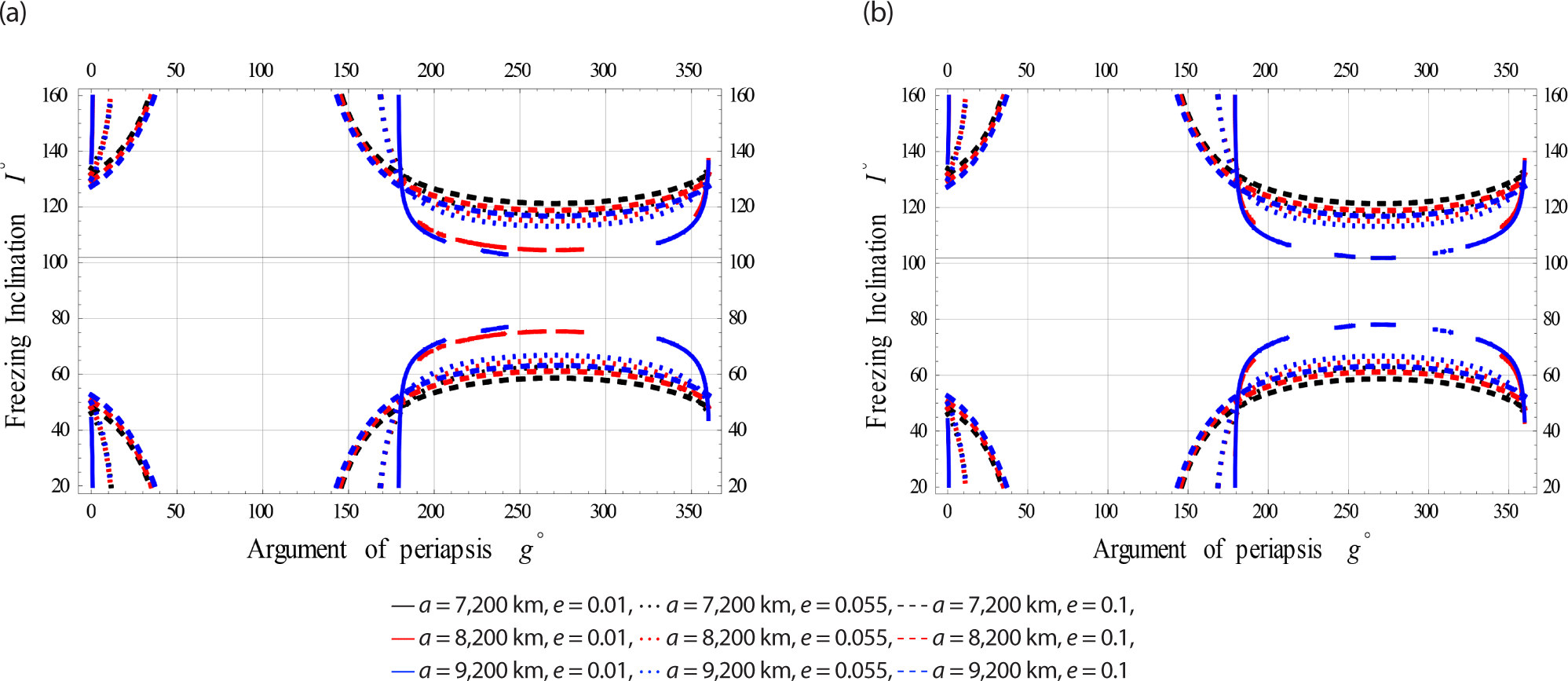
Fig. 1 simulate the impact of the frozen inclination (in degrees) concerning the argument of periapsis for satellites at Low Earth Orbits. These simulations are considered the gravitational effects (GE) influence alone and combined with EM effects, respectively.
jass-41-2-87-g1
Fig. 1. Freezing inclination vs. the argument of periapsis. (a) Gravitational effects (GE) on I vs. g for LEO. (b) The electromagnetic (EM) and gravitational effects (GE) on I vs. g for LEO.
Download Original Figure

The figures reveal that the freezing inclination could be obtained for the whole range of the argument of perapsis.

4.1.2 Case II: Satellites at Meduim Earth Orbits

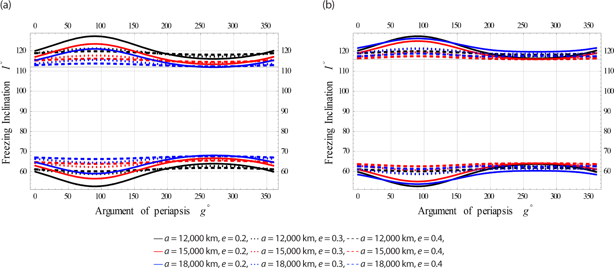
The same procedure is repeated but for Meduim Earth Orbits in Fig. 2.
jass-41-2-87-g2
Fig. 2. Freezing inclination vs. the argument of periapsis. (a) The gravitational effects (GE) on I vs. g for MEO. (b) The electromagnetic (EM) and gravitational effects (GE) on I vs. g for MEO.
Download Original Figure
4.1.3 Case III: Satellites at High Earth Orbits

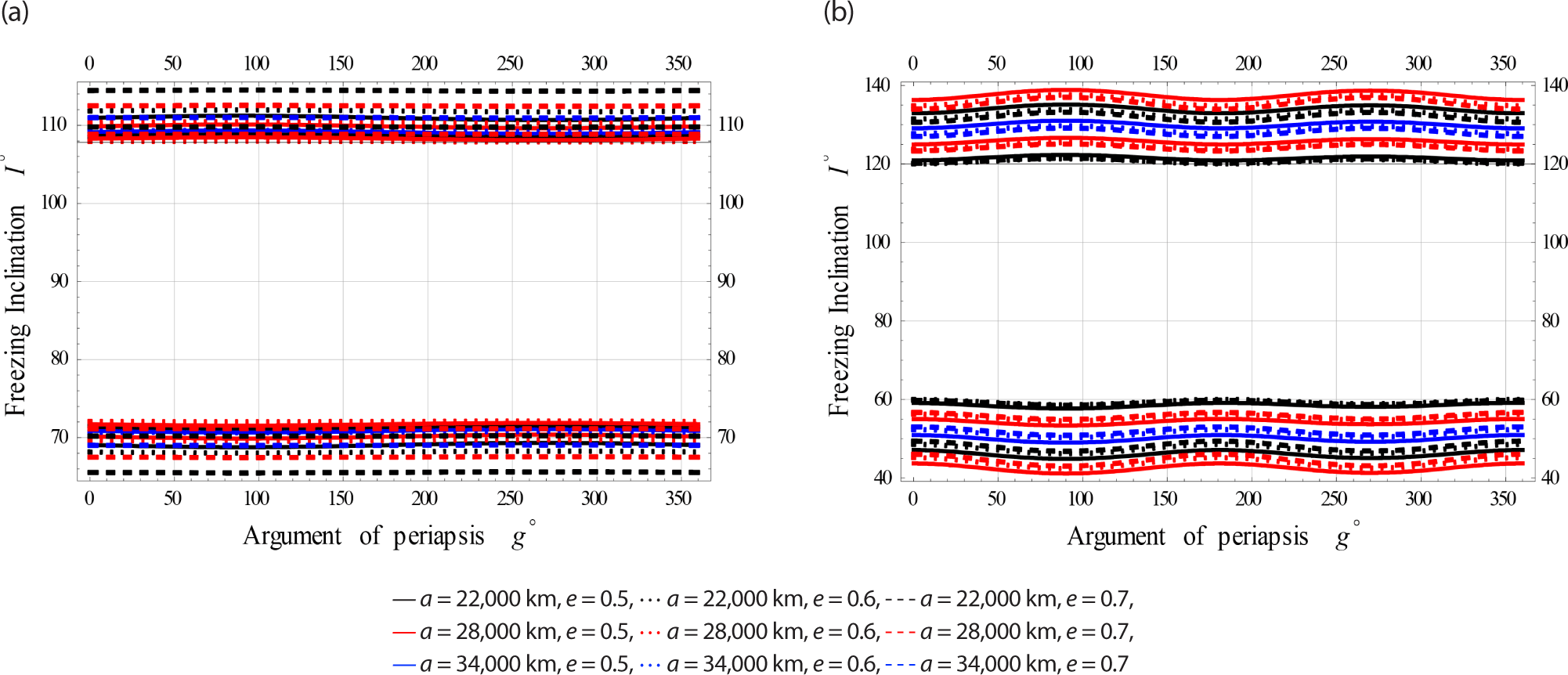
Also, the procedure ir repeated for High Earth Orbits in Fig. 3.
jass-41-2-87-g3
Fig. 3. Freezing inclination vs. the argument of periapsis. (a) The gravitational effects (GE) on I vs. g for HEO. (b) The electromagnetic (EM) and gravitational effects (GE) on I vs. g for HEO.
Download Original Figure

The color indicator of these Figs. are attached as legends next to each Fig. From all these Figs. the effect of EM field on the freezing inclination of a charged satellite in visible with different sizes of perturbations. In all these figures the obtained bands of freezing inclinations are dependent on the satellite’s altitude, as well as the orbiy’s eccentricity.

4.2 Freezing Inclination Vs. the Semi-Major Axis

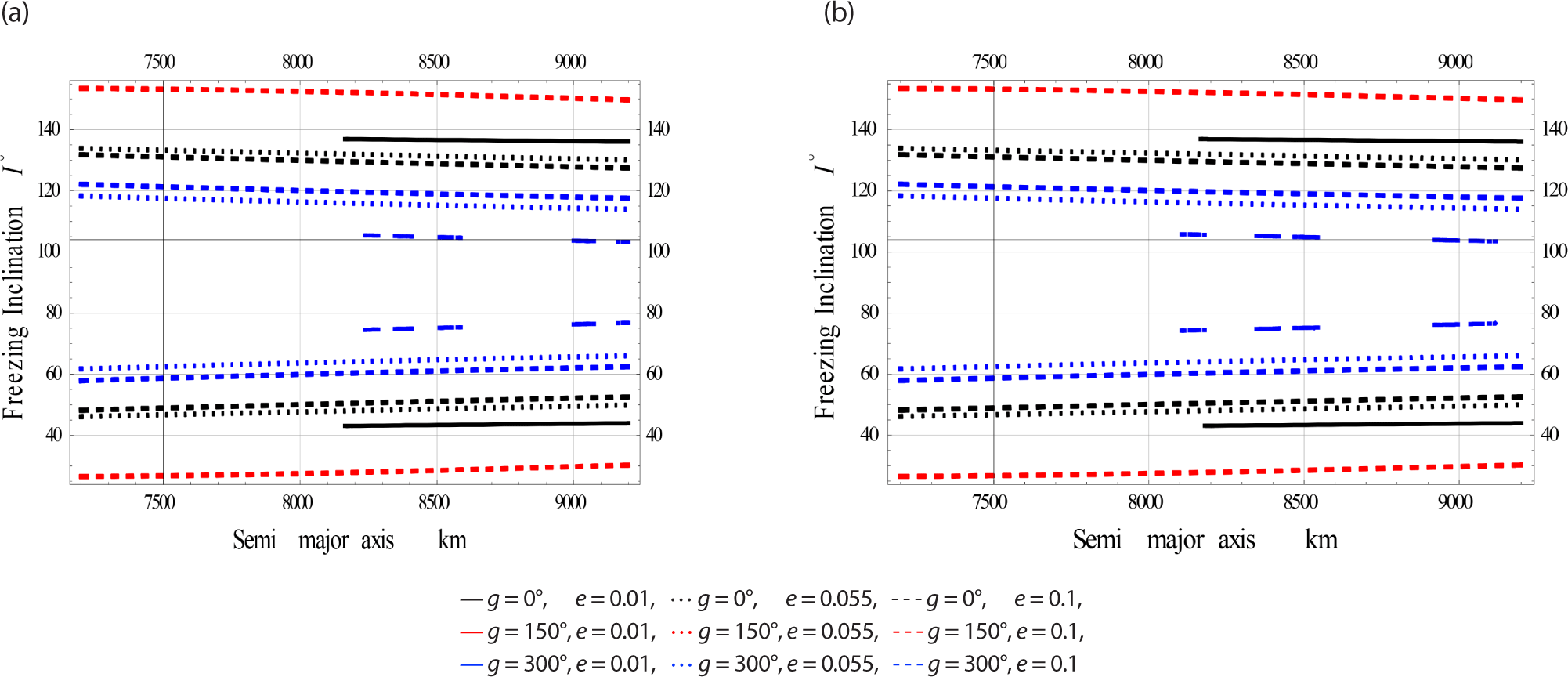
In this second secton. we will study the freezing inclination versus the semi-major axis for three subcases; namely Low, Medium, and High eccentricity Orbits considering (GE) influence alone and combined with EM effects, respectively.

4.2.1 Case I: Orbits withs Low Eccentricity

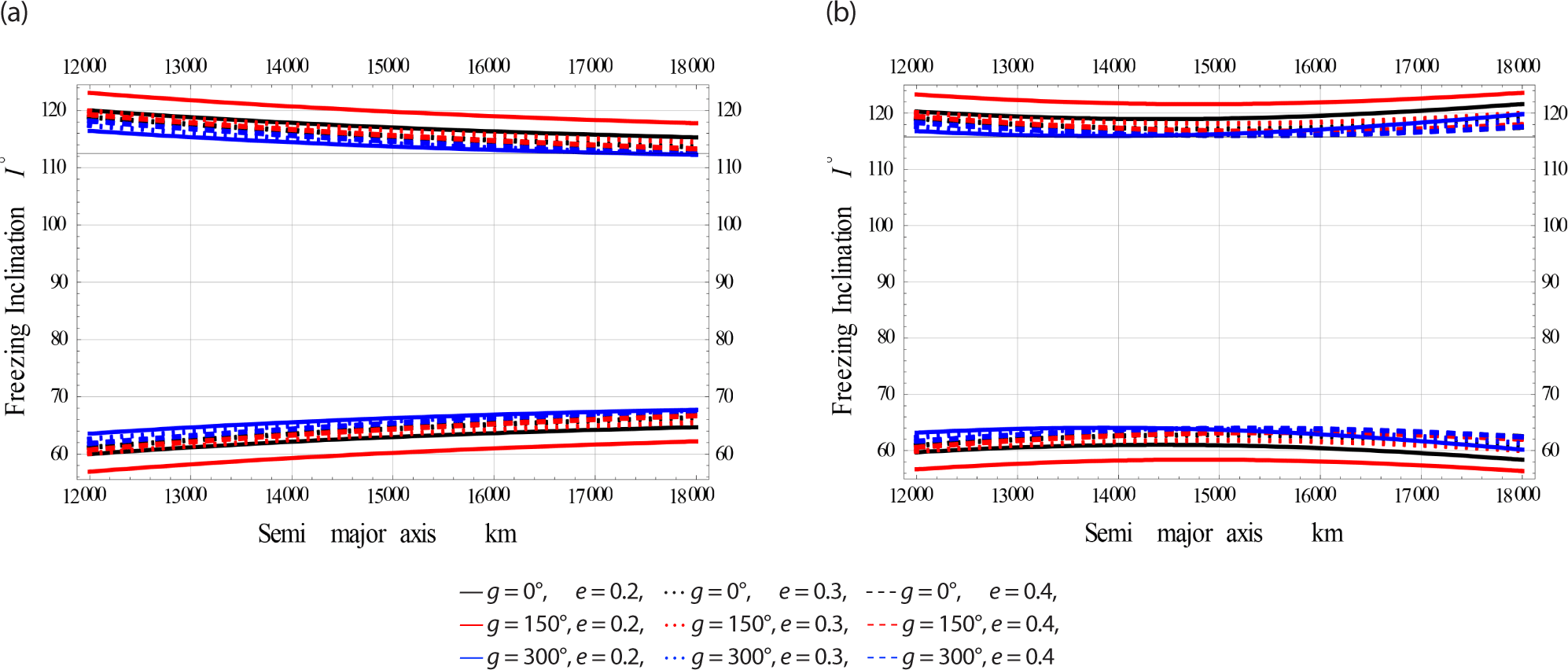
Fig. 4 simulate for Low Earth Orbits (in brief LEcO).
jass-41-2-87-g4
Fig. 4. Freezing inclination vs. the semi-majos axis. (a) The gravitational effects (GE) on I vs. a for LEcO. (b) The electromagnetic (EM) and gravitational effects (GE) on I vs. a for LEcO.
Download Original Figure
4.2.2 Case II: Orbits with Meduim Eccentricity

Fig. 5 simulate for Medium Earth Orbits (in brief MEcO).
jass-41-2-87-g5
Fig. 5. Freezing inclination vs. the semi-majos axis. (a) The gravitational effects (GE) on I vs. a for MEcO. (b) The electromagnetic (EM) and gravitational effects (GE) on I vs. a for MEcO.v
Download Original Figure
4.2.3 Case III: Orbits with High Eccentricity

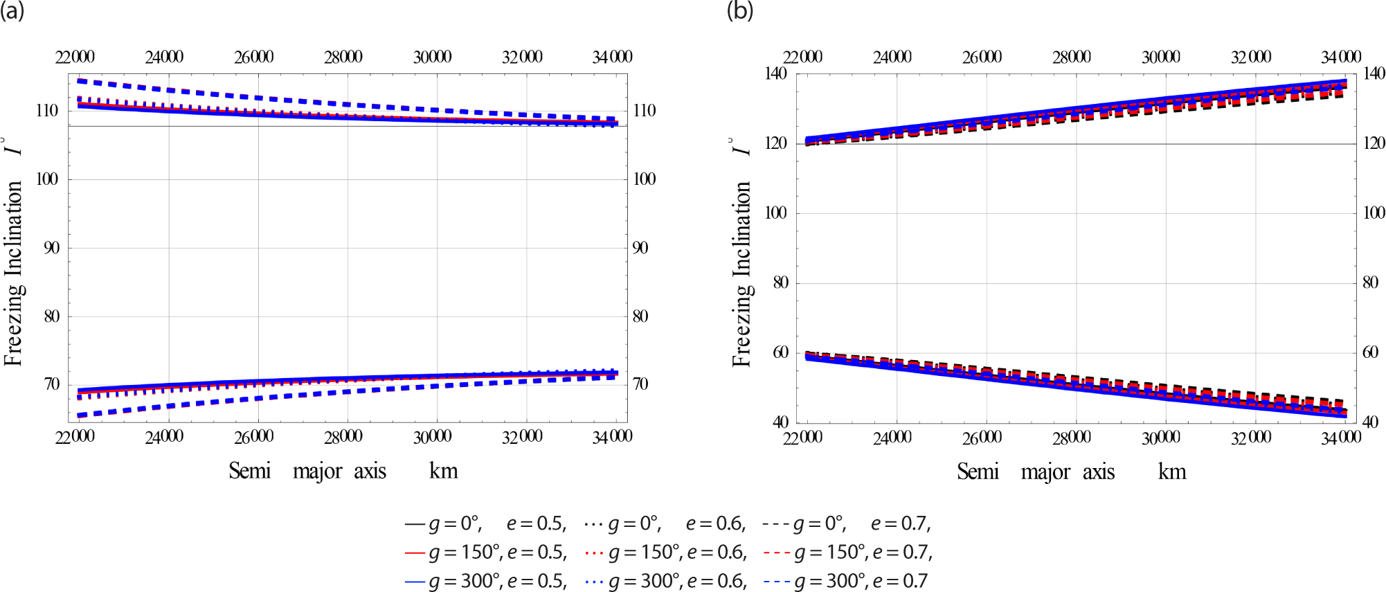
Fig. 6 simulate for High Earth Orbits (in brief HEcO).
jass-41-2-87-g6
Fig. 6. Freezing inclination vs. the semi-majos axis. (a) The gravitational effects (GE) on I vs. a for HEcO. (b) The electromagnetic (EM) and gravitational effects (GE) on I vs. a for HEcO.
Download Original Figure
4.3 Freezing Inclination Vs. the Eccentricity

In the last case, we plotted the freezing inclination in degrees versus the third independent parameter, namely the eccentricity for three subcases; namely Low, Medium, and High Earth Orbits considering (GE) influence alone and combined with EM effects, respectively.

4.3.1 Case I: Satellites at Low Earth Orbits

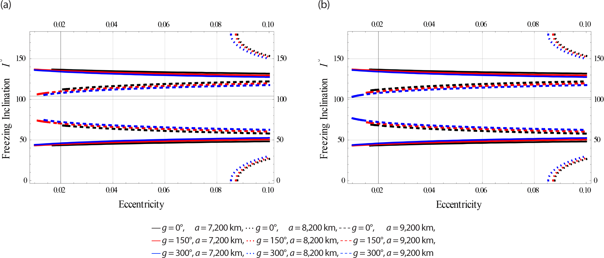
Fig. 7 are designed for Low Earth orbits.
jass-41-2-87-g7
Fig. 7. Freezing inclination vs. the eccentricity. (a) The gravitational effects (GE) on I vs. e for LEO. (b) The electromagnetic (EM) and gravitational effects (GE) on I vs. e for LEO.
Download Original Figure
4.3.2 Case II: Satellites at Meduim Earth Orbits

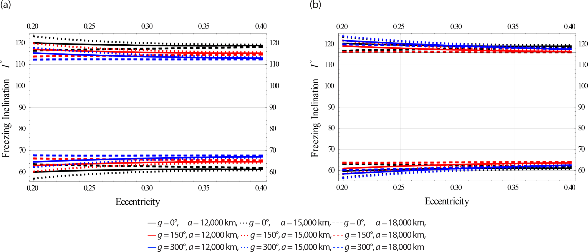
Fig. 8 have been done for Meduim Earth orbits.
jass-41-2-87-g8
Fig. 8. Freezing inclination vs. the eccentricity. (a) The gravitational effects (GE) on I vs. e for MEO. (b) The electromagnetic (EM) and gravitational effects (GE) on I vs. e for MEO.
Download Original Figure
4.3.3 Case III: Satellites at High Earth Orbits

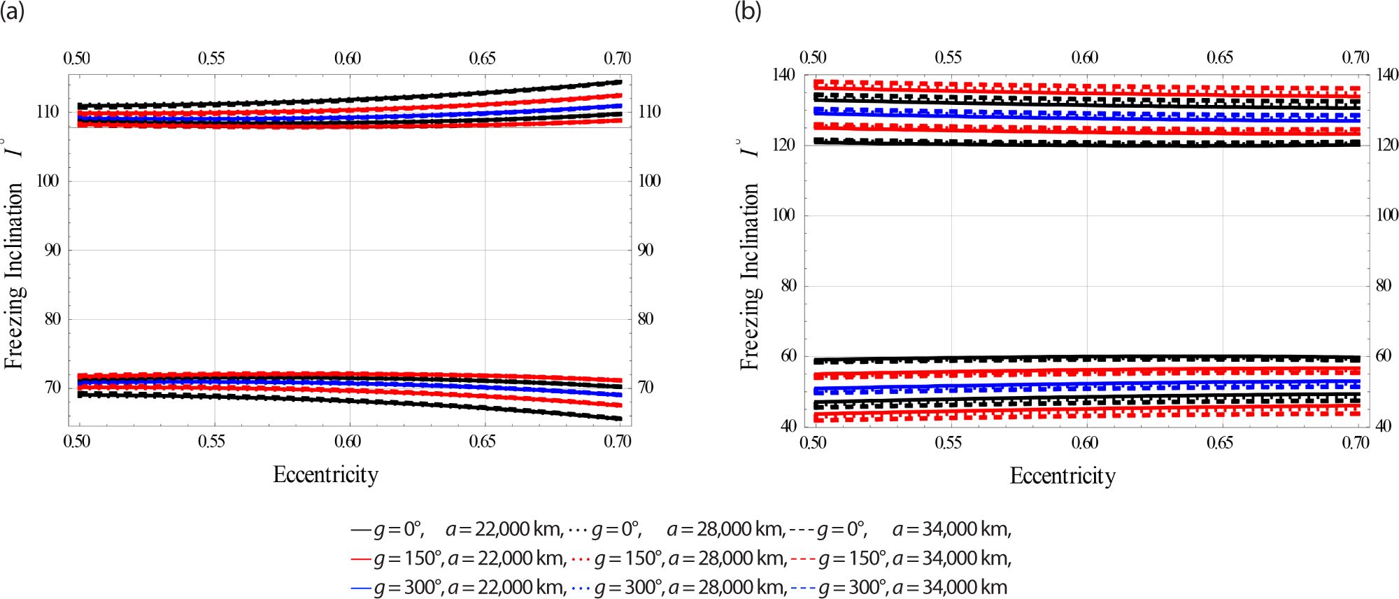
Fig. 9 have been done for High Earth orbits.
jass-41-2-87-g9
Fig. 9. Freezing inclination vs. the eccentricity. (a) The gravitational effects (GE) on I vs. e for HEO. (b) The electromagnetic (EM) and gravitational effects (GE) on I vs. e for HEO.
Download Original Figure

5. SOLUTION FOR THE ARGUMENT OF THE PERICENTRE

Eq. (4) is solved for the periapsis argument in this section. After a significant algebraic contribution, Eq. (4) may be rewritten as

G 4 sin 4 g + G 3 sin 3 g + G 2 sin 2 g + G 1 sin g + G 0 = 0
(9)

with

G 4 = 5 1024 A 2 , 6 { ( 12474 + 66906 C 2 + 36162 C 4 26019 C 6 ) e 4 η 3 , 12 + ( 504 + 26712 C 2 11592 C 4 + 1386 C 6 ) e 2 η 5 , 10 } ,
G 3 = 4 256 A 2 , 5 ( 105 + 1050 C 2 945 C 4 ) e η 5 , 8 ,
G 2 = 3 16 A 1 , 2 2 μ 2 [ 45 C 4 ( 5 η 5 , 7 + 7 η 3 , 9 ) ] 1 3 A 2 , 4 [ ( 63 η 5 , 6 + 77 η 3 , 8 ) C 4 ] + 3 16 A 1 , 2 2 μ 2 14 C 2 ( 5 η 5 , 7 + 7 η 3 , 9 ) 1 3 A 2 , 4 ( 24 η 5 , 6 40 η 3 , 8 ) C 2 1 2 Q 2 E ( 3 η 13 , 6 + η 11 , 4 ) C 2 1 3 A 2 , 4 { 5 η 5 , 6 + 7 η 3 , 8 } 1 2 Q 2 E { 5 η 13 , 6 3 η 11 , 4 } 5 1024 A 2 , 6 ( 105 1995 C 2 + 5355 C 4 3465 C 6 ) η 5 , 10 ( 1 + e 2 ) + 5 1024 A 2 , 6 { ( 12474 + 66906 C 2 + 36162 C 4 26019 C 6 ) e 4 η 3 , 12 + ( 504 + 26712 C 2 11592 C 4 + 1386 C 6 ) e 2 η 5 , 10 } ,
G 1 = 15 8 e A 2 , 3 [ 22 80 C 4 η 3 , 6 117 16 C 4 η 5 , 4 ] 15 8 e A 2 , 3 [ 33 10 C 2 η 3 , 6 + 44 10 C 2 η 5 , 4 ] 3 8 e A 2 , 3 { 5 η 3 , 6 6 η 5 , 4 } + 1 128 A 2 , 3 { 392 3 e η 3 , 6 27 e η 5 , 4 } C 6 1 64 A 2 , 5 ( 30 420 C 2 + 630 C 4 ) 1 e ( 1 + 18 e 2 ) η 5 , 8 3 256 A 2 , 5 ( 105 + 1050 C 2 945 C 4 ) e η 5 , 8
G 0 = 3 64 A 1 , 2 2 μ 2 { 245 C 4 η 3 , 8 + 25 C 4 η 5 , 6 + 144 C 4 η 6 , 5 } 3 64 A 1 , 2 2 μ 2 { 160 C 4 η 3 , 8 + 20 C 4 η 5 , 6 + 144 C 4 η 6 , 5 } 60 64 A 1 , 2 2 μ 2 η 3 , 8 C 6 + 3 128 A 2 , 4 { 1925 C 4 η 3 , 8 + 1155 C 4 η 5 , 6 } + 3 32 A 1 , 2 2 μ 2 [ 45 C 4 ( 5 η 5 , 7 + 7 η 3 , 9 ) ] + 1 6 A 2 , 4 [ ( 63 η 5 , 6 + 77 η 3 , 8 ) C 4 ] + 15 4 A 1 , 2 η 3 , 4 C 2 945 256 A 2 , 4 η 5 , 6 C 6 + 3 64 A 1 , 2 2 μ 2 ( 70 C 2 η 3 , 8 + 90 C 2 η 5 , 6 88 C 2 η 6 , 5 ) 3 64 A 1 , 2 2 μ 2 { 20 C 2 η 3 , 8 36 C 2 η 5 , 6 84 C 2 η 6 , 5 } + 3 128 A 2 , 4 { 1350 C 2 η 3 , 8 630 C 2 η 5 , 6 } + Q 2 E { 21 2 C 2 η 13 , 6 5 2 C 2 η 11 , 4 } + 3 32 A 1 , 2 2 μ 2 14 C 2 ( 5 η 5 , 7 + 7 η 3 , 9 ) + 1 6 A 2 , 4 ( 24 η 5 , 6 40 η 3 , 8 ) C 2 + 1 4 Q 2 E ( 3 η 13 , 6 + η 11 , 4 ) C 2 3 4 A 1 , 2 η 3 , 4 + 3 64 A 1 , 2 2 μ 2 { 35 η 3 , 8 + 25 η 5 , 6 + 16 η 6 , 5 } + 1 4 Q 2 E { 5 η 13 , 6 3 η 11 , 4 } + 3 128 A 2 , 4 { 105 η 3 , 8 + 45 η 5 , 6 } + 1 2 Q 2 E { 15 η 13 , 6 + 3 η 11 , 4 } + 1 6 A 2 , 4 { 5 η 5 , 6 + 7 η 3 , 8 } + 1 64 A 2 , 5 ( 270 + 5460 C 2 11550 C 4 + 2310 C 6 ) ( e + 6 e 3 ) η 3 , 10 + 1 256 A 2 , 5 ( 2202 + 5536 C 2 + 1333 C 4 140 C 6 ) e 3 η 3 , 10 + 1 512 A 2 , 6 { 229240 ( 1 + 5 e 2 + 1 8 e 4 ) η 3 , 12 50 ( 10 + 3 8 e 2 ) η 5 , 10 + [ 701820 ( 1 + 5 e 2 + 1 8 e 4 ) η 3 , 12 + 1050 ( 10 + 3 8 e 2 ) η 5 , 10 ] C 2 + [ 783300 ( 1 + 5 e 2 + 1 8 e 4 ) η 3 , 12 3150 ( 10 + 3 8 e 2 ) η 5 , 10 ] C 4 [ 214305 ( 1 + 5 e 2 + 1 8 e 4 ) η 3 , 12 2310 ( 10 + 3 8 e 2 ) η 5 , 10 ] C 6 } + 5 2048 A 2 , 6 { ( 525 17995 C 2 + 73605 C 4 79325.5 C 6 ) η 3 , 12 ( 2 e 2 + e 4 ) + ( 105 1995 C 2 + 5355 C 4 3465 C 6 ) η 5 , 10 ( 1 + e 2 ) } 5 8192 A 2 , 6 { ( 12474 + 66906 C 2 + 36162 C 4 26019 C 6 ) e 4 η 3 , 12 + ( 504 + 26712 C 2 11592 C 4 + 1386 C 6 ) e 2 η 5 , 10 } 3 2 A 22 ( 1 1 2 C 4 1 8 C 6 ) η 3 , 4 cos 2 ( Ω λ 2 , 2 )

6. DIFFERENT INVESTIGATED ORBITS OF EQ. (7)

In the following subsections, we will investigate three case studies, each of which contains three subcases. The first case studies the freezing ω versus I for three subcases; namely Low, Medium, and High Earth Orbits. The second case investigates the freezing ω versus the a for three subcases; namely Low, Medium, and High eccentricity Orbits. The third case studies the freezing ω versus e for three subcases; namely Low, Medium, and High Earth Orbits.

6.1 Freezing Argument of Periapsis Vs. Inclination

This section shows the the freezing ω (in degrees) concerning the orbital inclination.

6.1.1 Case I: Satellites at Low Earth Orbits

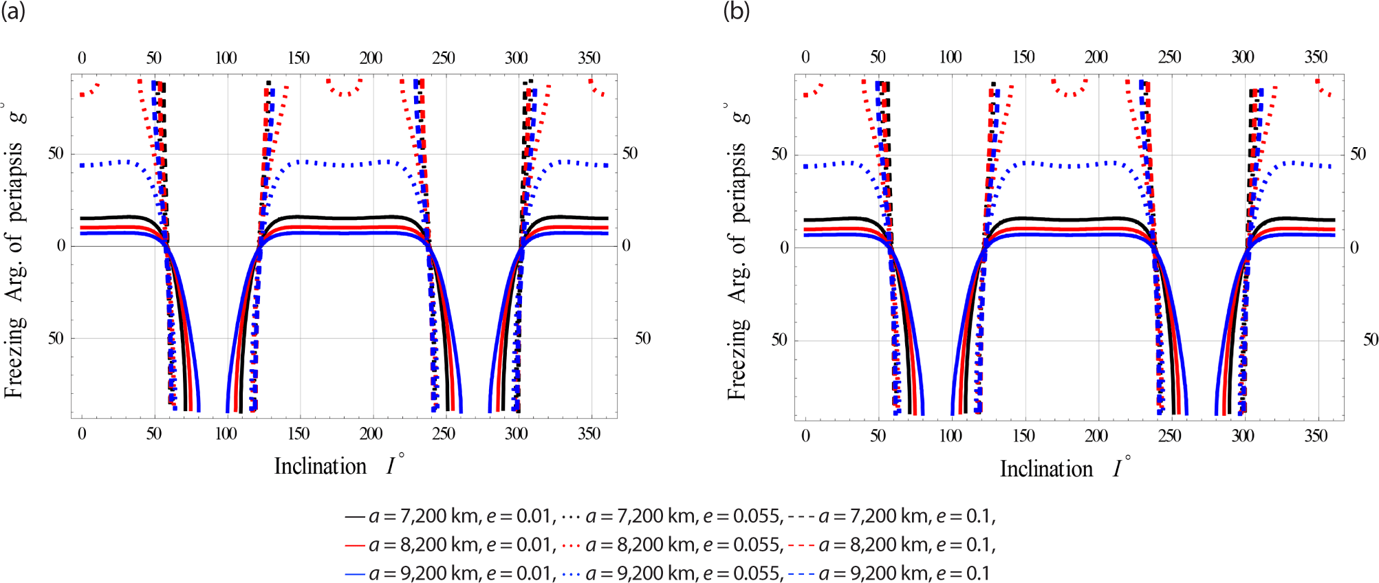
On Fig. 10, we plotted the freezing ω versus I for satellites at Low.
jass-41-2-87-g10
Fig. 10. Freezing argument of periapsis vs. inclination. (a) The gravitational effects (GE) on g vs. I for LEO. (b) The electromagnetic (EM) and gravitational effects (GE) on g vs. I for LEO.
Download Original Figure
6.1.2 Case II: Satellites at Meduim Earth Orbits

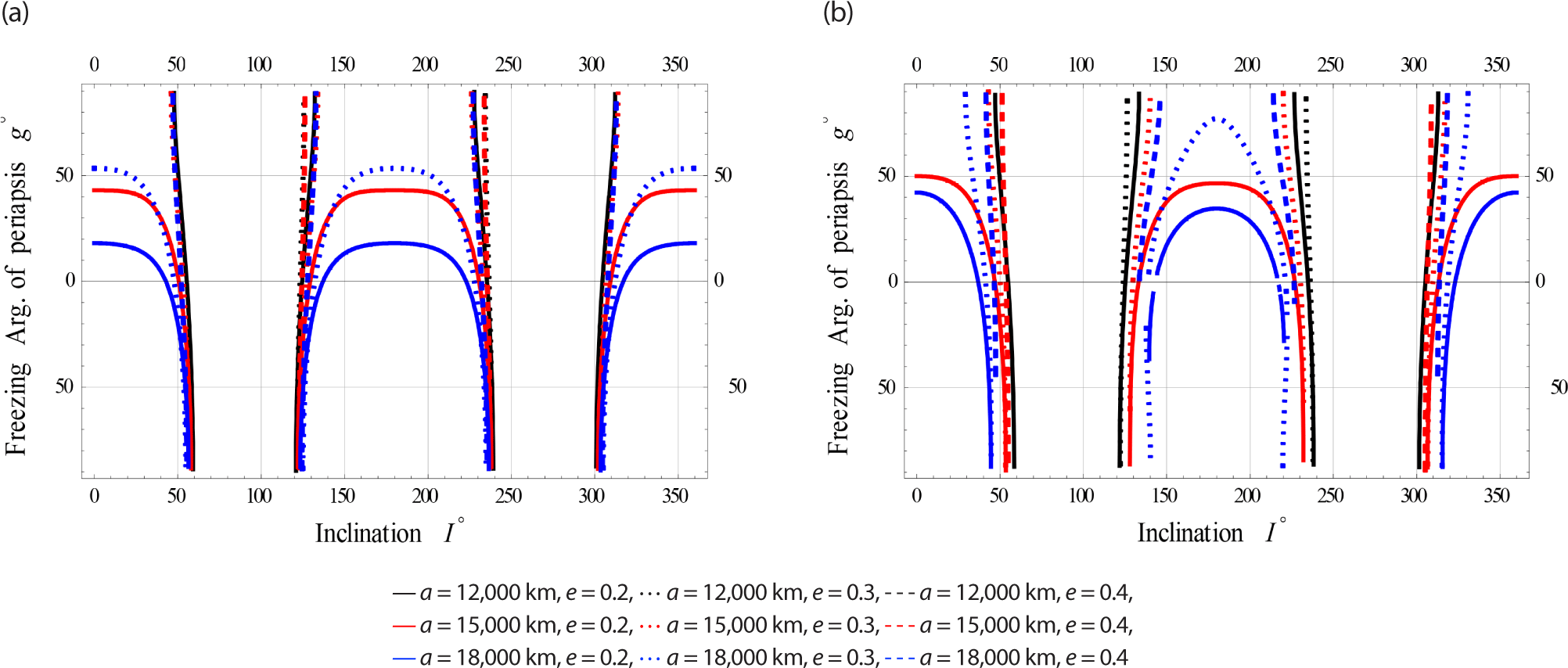
On Fig. 11, we plotted the freezing ω versus I for satellites at Meduim Earth Orbits respectively.
jass-41-2-87-g11
Fig. 11. Freezing argument of periapsis vs. inclination. (a) The gravitational effects (GE) on g vs. I for MEO. (b) The electromagnetic (EM) and gravitational effects (GE) on g vs. I for MEO.
Download Original Figure
6.1.3 Case III: Satellites at High Earth Orbits

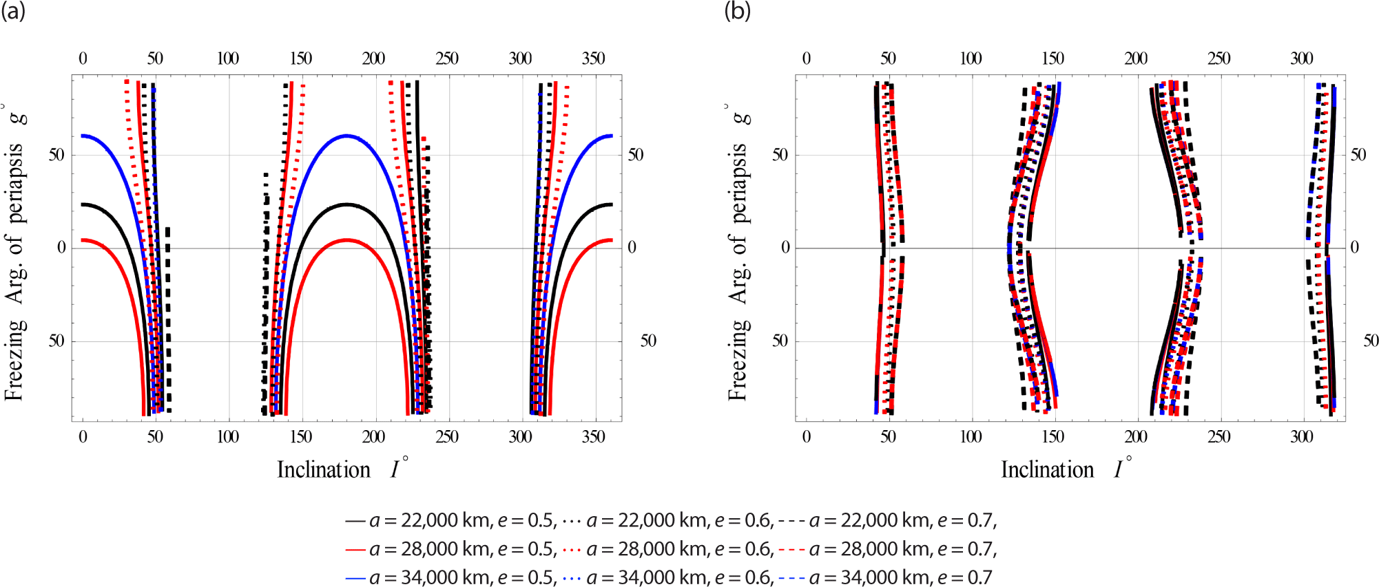
On Fig. 12, we plotted the freezing ω versus I for satellites at High Earth Orbits respectively.
jass-41-2-87-g12
Fig. 12. Freezing argument of periapsis vs. inclination. (a) The gravitational effects (GE) on g vs. I for HEO. (b) The electromagnetic (EM) and gravitational effects (GE) on g vs. I for HEO.
Download Original Figure

The (EM) perturbations on the dynamics of frozen orbits becomes worth, particularly in Medium and High Earth Orbits.

6.2 Freezing Argument of Periapsis Vs. Semi-Major

In this section we plotted the freezing ω versus some another independant parameter, namely the semi-major axis.

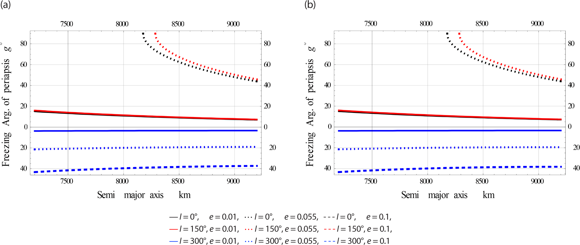
6.2.1 Case I: Orbits with Low Eccentricity

In Fig. 13, we plotted the freezing ω versus a for satellites at Low eccentricity Orbits. In this case the EM perturbation is very little, the dynamics shown in the Fig. 13(a) and (b) are nearly the same.
jass-41-2-87-g13
Fig. 13. Freezing argument of periapsis vs. semi-major axis. (a) The gravitational effects (GE) on g vs. a for LEcO. (b) The electromagnetic (EM) and gravitational effects (GE) on g vs. a for LEcO.
Download Original Figure
6.2.2 Case II: Orbits with Meduim Eccentricity

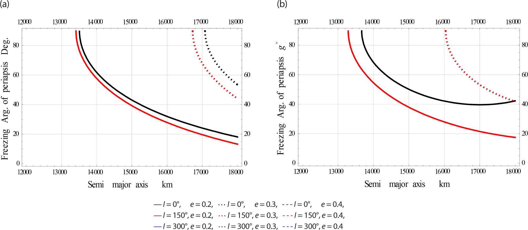
In Fig. 14, we plotted the freezing ω versus a for satellites at Meduim eccentricity Orbits.
jass-41-2-87-g14
Fig. 14. Freezing argument of periapsis vs. semi-major axis. (a) The gravitational effects (GE) on g vs. a for MEcO. (b) The electromagnetic (EM) and gravitational effects (GE) on g vs. a for MEcO.
Download Original Figure
6.2.3 Case III: Orbits with High Eccentricity

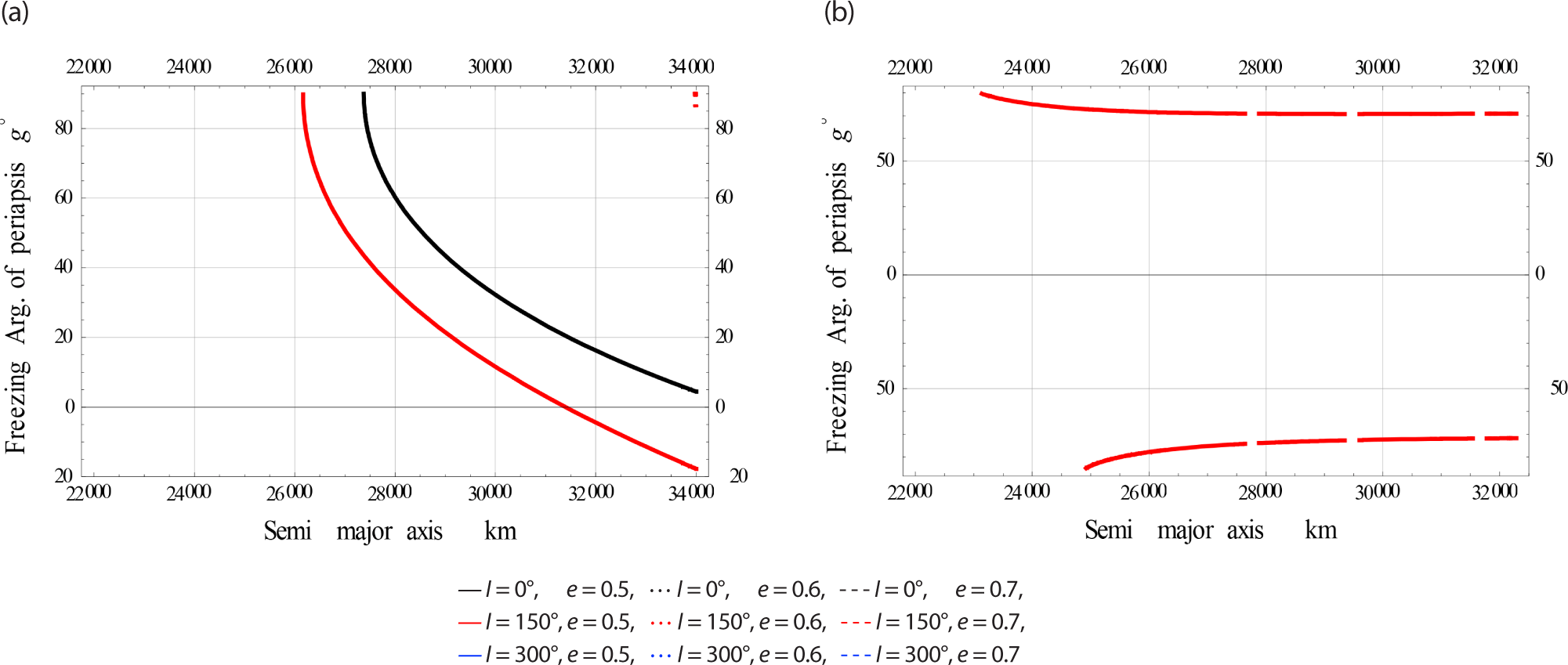
In Fig. 15, we plotted the freezing ω versus a for satellites at High eccentricity Orbits.
jass-41-2-87-g15
Fig. 15. Freezing argument of periapsis vs. semi-major axis. (a) The gravitational effects (GE) on g vs. a for HEcO. (b) The electromagnetic (EM) and gravitational effects (GE) on g vs. a for HEcO.
Download Original Figure

The effects on the frozen orbit dynamics when including the EM perturbations is clearly visible for MEcO and HEcO.

6.3 Freezing Argument of Periapsis Vs. Eccentricity

This section shows the the freezing ω (in degrees) concerning the orbital eccentricity.

6.3.1 Case I: Satellites at Low Earth Orbits

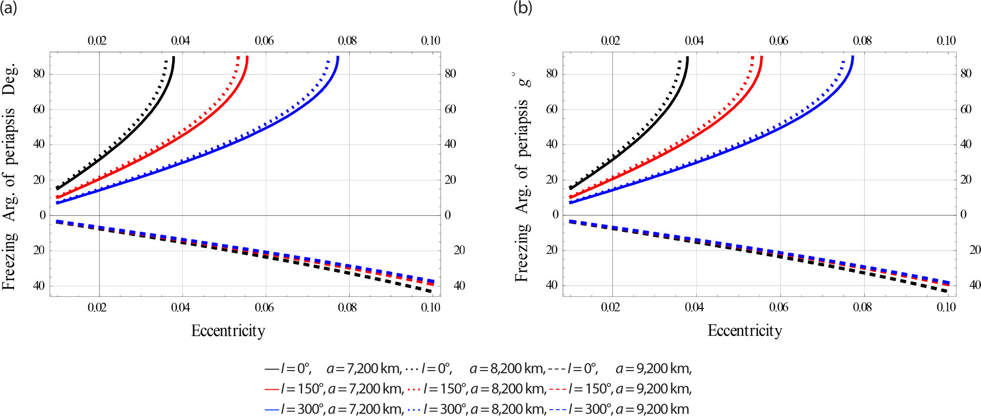
In Fig. 16, we plotted the freezing ω versus for satellites at Low Earth Orbits.
jass-41-2-87-g16
Fig. 16. Freezing argument of periapsis vs. eccentricity. (a) The gravitational effects (GE) on g vs. e for LEO. (b) The electromagnetic (EM) and gravitational effects (GE) on g vs. e for LEO.
Download Original Figure
6.3.2 Case II: Satellites at Meduim Earth Orbits

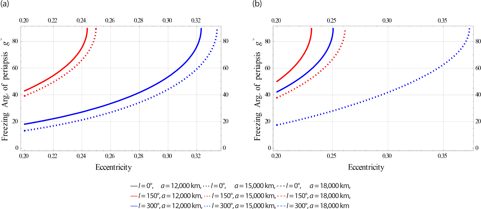
In Fig. 17, we plotted the freezing ω versus e for satellites at Meduim Earth Orbits.
jass-41-2-87-g17
Fig. 17. Freezing argument of periapsis vs. eccentricity. (a) The gravitational effects (GE) on g vs. e for MEO. (b) The electromagnetic (EM) and gravitational effects (GE) on g vs. e for MEO.
Download Original Figure
6.3.3 Case III: Satellites at High Earth Orbits

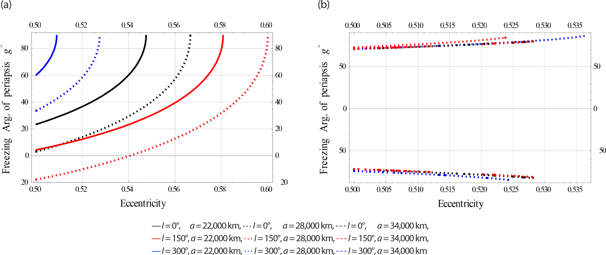
In Fig. 18, we plotted the freezing ω versus e for satellites at High Earth Orbits.
jass-41-2-87-g18
Fig. 18. Freezing argument of periapsis vs. eccentricity. (a) The gravitational effects (GE) on g vs. e for HEO. (b) The electromagnetic (EM) and gravitational effects (GE) on g vs. e for HEO.
Download Original Figure

The effects of electromagnetic (EM) disturbances on frozen orbit dynamics become significant, especially in the medium and high earth orbits.

7. THE FROZEN ECCENTRICITY

In this part, we will get a family of eccentricity frozen orbits around the Earth by using transformed Hamilton (1).

Employ the Hamiltonian canonical equation of motion, where dGdt=H1*g

H * g = 3 16 A 1 , 2 2 μ 2 ( 15 S 4 16 S 2 + 1 ) ( η 5 , 5 η 3 , 7 ) sin 2 g + 3 8 A 2 , 3 ( 5 S 3 4 S ) e η 3 , 5 cos g 1 3 A 2 , 4 ( 7 S 4 6 S 2 ) ( η 5 , 5 η 3.7 ) sin 2 g + 1 2 Q 2 E S 2 ( η 13 , 5 η 11 , 3 ) sin 2 g + 1 64 A 2 , 5 ( 240 840 S 2 + 630 S 4 ) ( e + 6 e 3 ) η 3 , 9 cos g + 3 256 A 2 , 5 ( 280 S 2 315 S 4 ) e 3 η 3 , 9 cos 3 g + 1 256 A 2 , 6 ( 1680 S 2 5040 S 4 + 3465 S 6 ) η 3 , 11 ( 5 2 e 2 + 5 4 e 4 ) sin 2 g + 5 2048 A 2 , 6 ( 1260 S 4 1386 S 6 ) e 4 η 3 , 11 sin 4 g
(10)

Using the Delaunay variable and Eq. (10), we obtain

e ˙ = 1 e 2 μ a e { 3 16 A 1 , 2 2 μ 2 ( 15 S 4 16 S 2 + 1 ) ( η 5 , 5 η 3 , 7 ) + 3 8 A 2 , 3 ( 5 S 3 4 S ) e η 3 , 5 cos g 2 3 A 2 , 4 ( 7 S 4 6 S 2 ) ( η 5 , 5 η 3 , 7 ) + 1 2 Q 2 E S 2 ( η 13 , 5 η 11 , 3 ) } sin g cos g + 1 64 A 2 , 5 ( 240 840 S 2 + 630 S 4 ) ( e + 6 e 3 ) η 3 , 9 cos g + 3 256 A 2 , 5 ( 280 S 2 315 S 4 ) e 3 η 3 , 9 cos g 3 64 A 2 , 5 ( 280 S 2 315 S 4 ) e 3 η 3 , 9 sin 2 g cos g + 5 512 A 2 , 6 ( 6720 e 2 + 1680 S 2 e 4 3780 S 4 e 4 ) + 6930 S 6 e 2 + 2079 S 6 e 4 ) η 3 , 11 sin g cos g 5 256 A 2 , 6 ( 1260 S 4 1386 S 6 ) e 4 η 3 , 11 cos g sin 3 g
(11)

impose the eccentricity to be equal zero to capture the frozen eccentricity and rearrange the equation, thus

e ˙ = ( ε 0 + ε 1 sin g + ε 2 sin 2 g + ε 3 sin 3 g ) cos g = 0
(12)

where

ε 0 = 3 8 A 2 , 3 1 e 2 μ a e ( 5 S 3 4 S ) e η 3 , 5 + 3 256 A 2 , 5 ( 280 S 2 315 S 4 ) e 3 η 3 , 9
ε 1 = 1 e 2 μ a e { 3 16 A 1 , 2 2 μ 2 ( 15 S 4 16 S 2 + 1 ) ( η 5 , 5 η 3 , 7 ) 2 3 A 2 , 4 ( 7 S 4 6 S 2 ) ( η 5 , 5 η 3 , 7 ) + 1 2 Q 2 E S 2 ( η 13 , 5 η 11 , 3 ) } + 5 512 A 2 , 6 ( 6720 e 2 + 1680 S 2 e 4 3780 S 4 e 4 + 6930 S 6 e 2 + 2079 S 6 e 4 ) η 3 , 11
ε 2 = 3 64 A 2 , 5 ( 280 S 2 315 S 4 ) e 3 η 3 , 9
ε 3 = 5 256 A 2 , 6 ( 1260 S 4 1386 S 6 ) e 4 η 3 , 11

Using Eq. (12), to get, ė = 0 as

i : cos g = 0 g = π 2
(13.1)
i i : ε 0 + ε 1 sin g + ε 2 sin 2 g + ε 3 sin 3 g = 0.
(13.2)

8. SOLUTION FOR INCLINATION

This section extends the concept of frozen eccentricity by manipulating the Hamiltonian equations in section 7 by considering the inclination parameter, demonstrating how freezing eccentricity can be achieved by using inclination as a parameter in the solution.

According to the powers of C, rewrite Eq. (11) as

1 512 [ 108 A 2 , 3 e η 3 , 5 5 A 2 , 6 e 2 ( 6930 + 2079 e 2 ) η 3 , 11 sin g 138605 A 2 , 6 e 4 η 3 , 11 sin 3 g ] C 6 [ 45 16 A 1 , 2 2 μ 2 ( η 5 , 5 η 3 , 7 ) sin 2 g 7 3 A 2 , 4 ( η 5 , 5 η 3 , 7 ) sin 2 g + 57 64 A 2 , 3 η 3 , 5 cos g ] C 4 + [ 21 8 A 1 , 2 2 μ 2 ( η 5 , 5 η 3 , 7 ) sin 2 g + 8 3 A 2 , 4 ( η 5 , 5 η 3 , 7 ) sin 2 g 9 16 A 2 , 3 η 3 , 5 cos g 1 2 Q 2 E ( η 13 , 5 η 11 , 3 ) sin 2 g ] C 2 1 3 A 2 , 4 ( η 5 , 5 η 3 , 7 ) sin 2 g + 1 2 Q 2 E ( η 13 , 5 η 11 , 3 ) sin 2 g + 15 8 A 2 , 3 η 3 , 5 cos g = 0
(14)
e ˙ = ε ˜ 3 ( C 2 ) 3 + ε ˜ 2 ( C 2 ) 2 + ε ˜ 1 C 2 + ε ˜ 0 = 0
(15)

where

ε ˜ 3 = 1 512 [ 108 A 2 , 3 η 3 , 5 5 A 2 , 6 e 2 ( 6930 + 2079 e 2 ) η 3 , 11 sin g 13860 A 2 , 6 e 4 η 3 , 11 sin 3 g ]
ε ˜ 2 = 45 16 A 1 , 2 2 μ 2 ( η 5 , 5 η 3 , 7 ) sin 2 g 7 3 A 2 , 4 ( η 5 , 5 η 3 , 7 ) sin 2 g + 57 64 A 2 , 3 η 3 , 5 cos g
ε ˜ 1 = 21 8 A 1 , 2 2 μ 2 ( η 5 , 5 η 3 , 7 ) sin 2 g + 8 3 A 2 , 4 ( η 5 , 5 η 3 , 7 ) sin 2 g 9 16 A 2 , 3 η 3 , 5 cos g
ε ˜ 0 = 1 3 A 2 , 4 ( η 5 , 5 η 3 , 7 ) sin 2 g + 1 2 Q 2 E S 2 ( η 13 , 5 η 11 , 3 ) sin 2 g 15 8 A 2 , 3 η 3 , 5 cos g

In order to examine Eq. (15) in further detail, we will visualize it in the next section.

8.1 Three Dimensional Graphical Representation of Eq. (15)

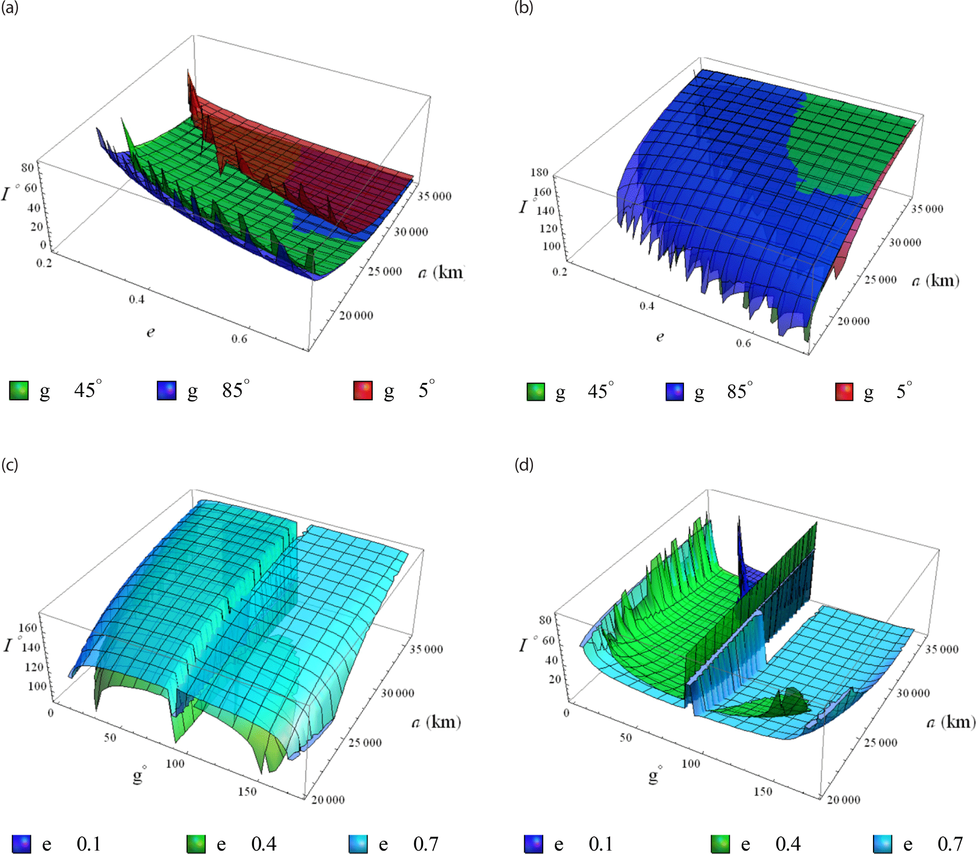
In order to visualize Eq. (15), we have found using MATHEMATICA software only two real roots of the algebraic Eq. (15). To freez the eccentricity we use the inclination as a freezing parameter. Three-dimensional graphs of the freezing inclination against two parameters (the semi-major axis and the eccentricity) are presented in Figs. 19(a) and (b), using three different values for the argument of periapsis. Also, other graphs are introduced against two parameters (the semi-major axis and the the argument of periapsis) in Figs. 19(c) and (d), using three values of eccentricities.
jass-41-2-87-g19
Fig. 19. Freezing inclination. (a) 3D plot for the 2nd root at different argument of periapses. (b) 3D plot for the 4th root at different argument of periapses. (c) 3D plot for the 2nd root at different eccentricities. (d) 3D plot for the 4th root at different eccentricities.
Download Original Figure

Remark. Each two real roots of Eq. (15) will not close up the whole domain of the inclination or the argument of periapsis smoothly, it is very clear from the wavy edges of each root. This is due to the fact that the the frozen orbits are equilibruim solutions at some critical values of the orbital elements; e.g. critical inclination. This ensures that there exist a bifurcation structure near to these critical values.

8.2 The Eccentricity Vector’s Phase Space

Use the non-singular variables to define the eccentricity vector’s polar coordinate as:

h ˜ = e sin g , k ˜ = e cos g
(16)
h ˜ ˙ = e ˙ sin g + e g ˙ cos g , k ˜ ˙ = e ˙ cos g e g ˙ sin g
(17)
d h ˜ d k ˜ = h ˜ ˙ k ˜ ˙ = e ˙ sin g + e g ˙ cos g e ˙ cos g e g ˙ sin g
(18)
h ˜ = e ˙ sin g + e g ˙ cos g e ˙ cos g e g ˙ sin g k ˜
(19)

where ė, ġ are given by

e ˙ = 3 16 A 1 , 2 2 μ 2 e ( 15 ( 1 2 C 2 + C 4 ) 16 ( 1 C 2 ) + 1 ) ( η 7 , 4 η 5 , 6 ) sin 2 g + 3 8 A 2 , 3 ( 5 ( 1 C 2 ) 3 2 4 ( 1 C 2 ) 1 2 ) η 5 , 4 cos g 1 3 e A 2 , 4 ( 7 ( 1 2 C 2 + C 4 ) 6 ( 1 C 2 ) ) ( η 7 , 4 η 5 , 6 ) sin 2 g + 3 256 A 2 , 5 ( 280 S 2 315 S 4 ) e 2 η 5 , 8 [ 1 4 sin 2 g ] cos g + 5 512 A 2 , 6 ( 6930 S 6 6720 + [ 1680 3780 S 2 + 2079 S 4 ] S 2 e 2 ) e η 5 , 10 sin g cos g 5 256 A 2 , 6 ( 1260 S 4 1386 S 6 ) e 3 η 5 , 10 cos g sin 3 g + 1 2 e Q 2 E S 2 ( η 11 , 4 η 9 , 2 ) sin 2 g
(20)
g ˙ = 15 4 A 1 , 2 η 3 , 4 C 2 + 3 64 A 1 , 2 2 μ 2 { 90 η 3 , 8 + 126 η 5 , 6 4 η 6 , 5 } C 2 3 4 A 1 , 2 η 3 , 4 + 3 64 A 1 , 2 2 μ 2 { 35 η 3 , 8 + 25 η 5 , 6 + 16 η 6 , 5 } 3 128 A 2 , 4 { 105 η 3 , 8 + 45 η 5 , 6 } + 1 2 Q 2 E { 15 η 13 , 6 + 3 η 11 , 4 } + 1 6 A 2 , 4 { 5 η 5 , 6 + 7 η 3 , 8 } cos 2 g + 1 4 Q 2 E { 5 η 13 , 6 3 η 11 , 4 } cos 2 g 3 8 e A 2 , 3 { 5 η 3 , 6 6 η 5 , 4 } sin g + 3 128 A 2 , 4 { 1350 η 3 , 8 630 η 5 , 6 } C 2 + 42 32 A 1 , 2 2 μ 2 ( 5 η 5 , 7 + 7 η 3 , 9 ) C 2 cos 2 g + 1 6 A 2 , 4 ( 24 η 5 , 6 40 η 3 , 8 ) C 2 cos 2 g + 1 2 Q 2 E { 21 η 13 , 6 5 η 11 , 4 } C 2 + 1 4 Q 2 E { 3 η 13 , 6 + η 11 , 4 } C 2 cos 2 g + 3 16 e A 2 , 3 { 33 η 3 , 6 44 η 5 , 4 } C 2 sin g + 3 64 A 1 , 2 2 μ 2 { 85 η 3 , 8 + 5 η 5 , 6 } C 4 + 3 128 A 2 , 4 { 1925 η 3 , 8 + 1155 η 5 , 6 } C 2 + 135 32 A 1 , 2 2 μ 2 { 5 η 5 , 7 7 η 3 , 9 } C 4 cos 2 g + 1 6 A 2 , 4 { 63 η 5 , 6 + 77 η 3 , 8 } C 4 cos 2 g 15 640 e A 2 , 3 { 22 η 3 , 6 585 η 5 , 4 } C 4 sin g 60 64 A 1 , 2 2 μ 2 η 3 , 8 + 1 128 A 2 , 3 { 392 3 e η 3 , 6 27 e η 5 , 4 } sin g 945 256 A 2 , 4 η 5 , 6 + 1 256 A 2 , 5 { 9240 ( e + 6 e 3 ) η 3 , 10 140 e 3 η 3 , 10 sin 3 g } C 6 1 512 A 2 , 6 { 214305 ( 1 + 5 e 2 + 1 8 e 4 ) η 3 , 12 2310 ( 10 + 3 8 e 2 ) η 5 , 10 } C 6 + 5 8192 A 2 , 6 { ( 317310 ( 2 e 2 + e 4 ) η 3 , 12 13860 ( 1 + e 2 ) η 5 , 10 ) cos 2 g ( 26019 e 4 η 3 , 12 + 1386 e 2 η 5 , 10 ) cos 4 g } c 6 + 3 12 A 22 η 3 , 4 c 6 cos F 0 , 0 2. 2 + 1 256 A 2 , 5 { ( 46200 ( e + 6 e 3 ) η 3 , 10 2520 1 e ( 1 + 18 e 2 ) η 5 , 8 ) sin g + ( 1333 e 3 η 3 , 10 + 945 e η 5 , 8 C 4 ) sin 3 g } C 4 1 512 A 2 , 6 { 783300 ( 1 + 5 e 2 + 1 8 e 4 ) η 3 , 12 3150 ( 10 + 3 8 e 2 ) η 5 , 10 } C 4 + 5 8192 A 2 , 6 { ( 294405 ( 2 e 2 + e 4 ) η 3 , 12 + 21420 ( 1 + e 2 ) η 5 , 10 ) cos 2 g ( 36162 e 4 η 3 , 12 11592 e 2 η 5 , 10 ) cos 4 g } C 4 + 3 4 A 22 η 3 , 4 C 4 cos 2 ( Ω λ 2 , 2 ) + 1 256 A 2 , 5 { ( 21840 ( e + 6 e 3 ) η 3 , 10 + 1680 1 e ( 1 + 18 e 2 ) η 5 , 8 ) sin g + ( 5536 e 3 η 3 , 10 1050 e η 5 , 8 ) sin 3 g } C 2 1 512 A 2 , 6 { 701820 ( 1 + 5 e 2 + 1 8 e 4 ) η 3 , 12 + 1050 ( 10 + 3 8 e 2 ) η 5 , 10 } C 2 + 5 8192 A 2 , 6 { ( 71980 ( 2 e 2 + e 4 ) η 3 , 12 7980 ( 1 + e 2 ) η 5 , 10 ) cos 2 g ( 66906 e 4 η 3 , 12 + 26712 e 2 η 5 , 10 ) cos 4 g } C 2 + 1 256 A 2 , 5 { ( 1080 ( e + 6 e 3 ) η 3 , 10 120 1 e ( 1 + 18 e 2 ) η 5 , 8 ) sin g ( 2202 e 3 η 3 , 10 + 105 e η 5 , 8 ) sin 3 g } 1 512 A 2 , 6 { 229240 ( 1 + 5 e 2 + 1 8 e 4 ) η 3 , 12 50 ( 10 + 3 8 e 2 ) η 5 , 10 } + 5 8192 A 2 , 6 { ( 2100 ( 2 e 2 + e 4 ) η 3 , 12 + 420 ( 1 + e 2 ) η 5 , 10 ) cos 2 g ( 12474 e 4 η 3 , 12 + 504 e 2 η 5 , 10 ) cos 4 g } 3 2 A 22 η 3 , 4 cos 2 ( Ω λ 2 , 2 )
(21)
8.3 Eccentricity Vector’s Portraits in 3D and 2D Phase Space

Interpreting the phase space of the eccentricity vector provides a comprehensive understanding of the orbital dynamics. It allows for predictions about the long-term evolution of orbits, helping to assess the stability and sustainability of orbits over extended periods. Also, t can reveal invariant manifolds that remain unchanged despite gravitational perturbations which associated with stable or unstable orbits.

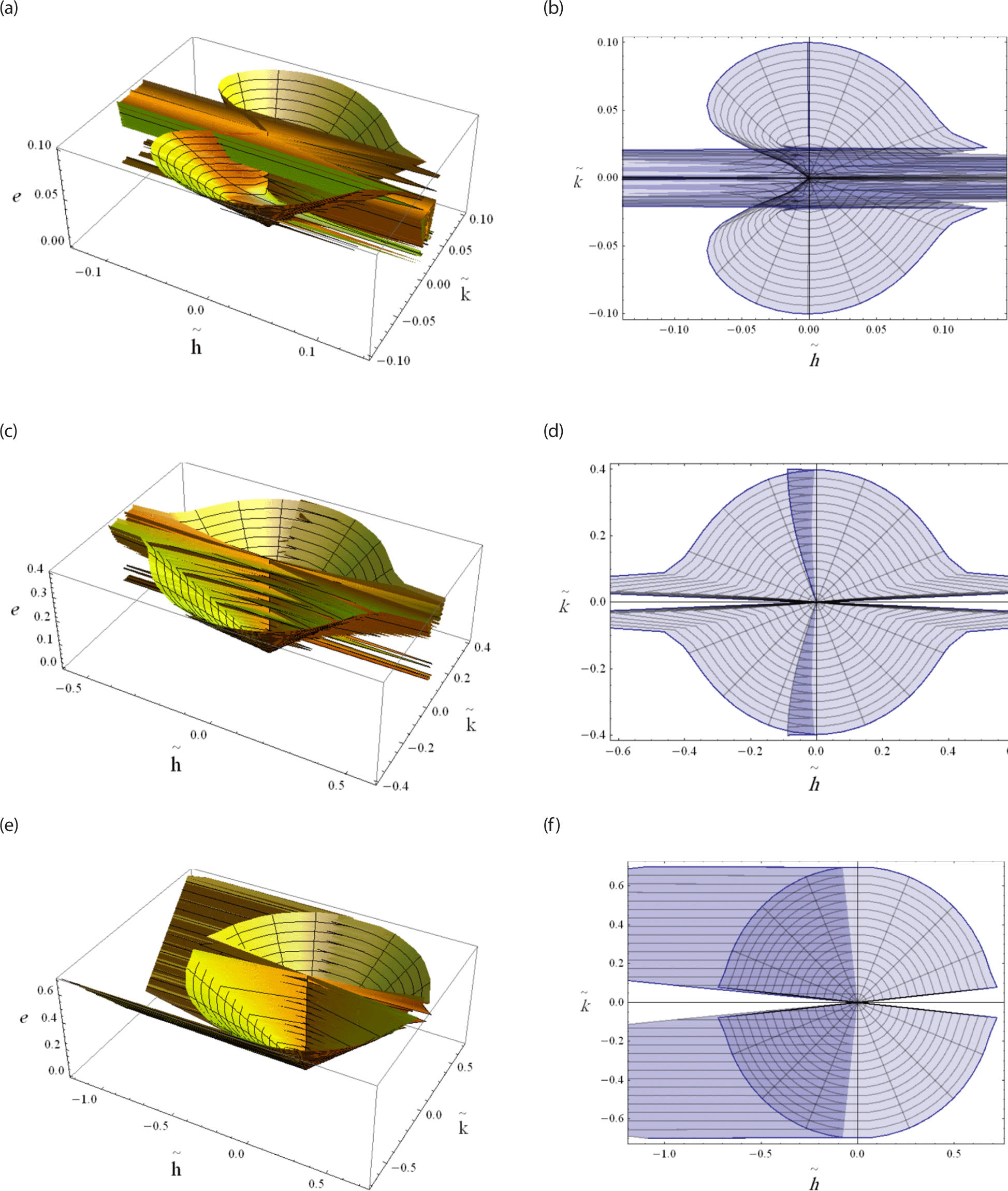
The eccentricity vector locus using the nonsingular variables (h˜,k˜) is represented either as a 3D and 2D projection onto (h˜,k˜) plane. In Fig. 20(a) the behaviour of the eccentricity vector is visualized for low earth orbits a = 7,200 km as well as for a very narrow range of eccentricity e ∈ [10–20, 0.1]. Its corresponding projection onto 2D is shown in Fig. 20(b). In Fig. 20(c), similar illustrations are obtained for the meduim a = 15,000 km Earth orbits, but with a relatively wide range of eccentricity e ∈ [10–20, 0.4]. The corresponding projection onto 2D is dipicted in Fig. 20(d). Finally in Fig. 20(e) similar illustrations are obtained for the high a = 36,000 km Earth orbits, but with a wide range of eccentricity e ∈ [10–20, 0.7]. The corresponding projection onto 2D is dipicted in Fig. 20(f).
jass-41-2-87-g20
Fig. 20. Eccentricity vector's portraits. (a) The locus of the eccentricity vector a = 7,200 km, e ∈ [10–20, 0.1]. (b) The projected phase space of Fig. 20(a) onto (h˜,k˜) plane. (c) The locus of the eccentricity vector a = 15,000 km, e ∈ [10–20, 0.4]. (d) The projected phase space of Fig. 20(c) onto (h˜,k˜) plane. (e) The locus of the eccentricity vector a = 36,000 km, e ∈ [10–20, 0.7]. (f) The projected phase space of Fig. 20(e) onto (h˜,k˜) plane (Continued on the next page.).
Download Original Figure

9. CONCLUDING REMARKS AND FUTURE WORKS

Section 1 of this book provides a brief introduction that focuses on earlier research in the topic of study. The focus is on the key components of the current work. Section 2 provides the initial normalized Hamiltonian, which is then used in the following sections to compute several families of the long-term frozen orbits of a charged satellite in the relevant model in the subsequent sections 4, 5, 6, 7, 8, 9 and 10. To study these obtained frozen orbits MATHEMATICA CODE is constructed. Using the inclination as a freezing parameter, some kinds of orbits ranges from a very low Earth orbits to a very high Earth orbits and enjoy a very low eccentricity to very high eccentricity are invistigated see Figs. 19. The same is done for considering the argument of periapsis as a freezing parameter, see Figs. 1018 and their analysis. The ranges that guarantee the frozen orbits are deduced from the figures.

See Fig. 19 for three-dimensional representations of the freezing inclination versus the semi-major axis and the eccentricity (as shown in Figs. 19(a) and (b)) and versus the semi-major axis and the argument of periapsis (as shown in Figs. 19(c) and (d)). Using the non-singular variables (h˜,k˜), the eccentricity vector’s phase space is represented. Three dimentional plots and its projection onto (h˜,k˜) plane are analyzed, see Fig. 20. In all the investigated cases, the effect of EM field on the freezing inclination of a charged satellite is clearly visible.

In the future, we aim to employ our model in actual space missions conducted within its orbital framework to refine the model based on observational data gathered from these missions. Additionally, our objectives include enhancing the realism of the model through the following measures:

  1. Incorporating the Poynting–Robertson drag force to account for the influence of charged particles.

  2. Investigating the impacts of EM field communication satellites when they are charged and operational within the ionosphere.

  3. Examining bifurcation surfaces within a comprehensive parameter space, alongside exploring the evolution of families in relation to physical parameters, inclination, and eccentricity.

  4. Applying the study to motion around prolate bodies, particularly in light of recent missions to variously shaped objects within the solar system.

ACKNOWLEDGMENTS

The authors would like to express their profound gratitude to the reviewers and the editorial team for their constructive criticism and highly productive discussions, which significantly contributed to the improvement of the manuscript.

REFERENCES

1.

Abd El-Bar SE, Abd El-Salam FA, Modelling of charged satellite motion in Earth’s gravitational and magnetic fields, Astrophys. Space Sci. 363, 89 (2018).

2.

Abd El-Salam FA, Abd El-Bar SE, Families of frozen orbits of lunar artificial satellites, Appl. Math. Model. 40, 9739-9753 (2016).

3.

Abd El-Salam FA, Abd El-Bar SE, Rassem M, Fully analytical solution of the electromagnetic perturbations on the motion of the charged satellites in Earth’s magnetic field, Eur. Phys. J. Plus. 132, 198 (2017).

4.

Abd El-Salam FA, Alamri SZ, Abd El-Bar SE, Seadawy AR, Frozen apsidal line orbits around tiaxial Moon with coupling quadrupole nonlinearity, Results Phys. 10, 176-186 (2018).

5.

Abdel-Aziz YA, Khalil KI, Electromagnetic effects on the orbital motion of a charged spacecraft, Res. Astron. Astrophys. 14, 589-600 (2014).

6.

Abdel‐Aziz YA, Lorentz force effects on the orbit of a charged artificial satellite: a new approach, AIP Conf. Proc. 888, 385-391 (2007).

7.

Ahmed MKM, On the normalization of the perturbed Keplerian systems, Astron. J. 107, 1900-1903 (1994).

8.

Atchison JA, Peck MA, Lorentz-augmented Jovian orbit insertion, J. Guid. Control Dyn. 32, 418-423 (2009).

9.

Carvalho JPS, Vilhena de Moraes R, Prado AFBA, Some orbital characteristics of lunar artificial satellites, Celest. Mech. Dyn. Astron. 108, 371-388 (2010).

10.

Circi C, D’Ambrosio A, Lei H, Ortore E, Global mapping of asteroids by frozen orbits: the case of 216 kleopatra, Acta Astronaut. 161, 101-107 (2019).

11.

Delhaise F, Morbidelli A, Luni-solar effects of geosynchronous orbits at the critical inclination, Celest. Mech. Dyn. Astron. 57, 155-173 (1993).

12.

Delsate N, Robutel P, Lemaître A, Carletti T, Frozen orbits at high eccentricity and inclination: application to Mercury orbiter, Celest. Mech. Dyn. Astron. 108, 275-300 (2010).

13.

Haberman R, Rand R, Yuster T, Resonant capture and separatrix crossing in dual-spin spacecraft, Nonlinear Dyn. 18, 159-184 (1999).

14.

Kamel AA, Perturbation method in the theory of nonlinear oscillations, Celest. Mech. 3, 90-106 (1970).

15.

Khattab EH, Radwan M, Rahoma WA, Frozen orbits construction for a lunar solar sail, J. Astron. Space Sci. 37, 1-9 (2020).

16.

Lanchares V, Pascual AI, San Juan JF, Frozen orbits around a prolate body, Monogr. Real Acad. Ci. Zaragoza. 35, 73-81 (2011).

17.

Lara M, Palacián JF, Russell RP, Mission design through averaging of perturbed Keplerian systems: the paradigm of an Enceladus orbiter, Celest. Mech. Dyn. Astron. 108, 1-22 (2010a).

18.

Lara M, Palacián JF, Yanguas P, Corral C, Analytical theory for spacecraft motion about mercury, Acta Astronaut. 66, 1022-1038 (2010b).

19.

Li LS, Influence of the electric induction drag on the orbit of a charged satellite moving in the ionosphere (solution by the method of the average value), Astrophys. Space Sci. 361, 1-8 (2016).

20.

Li X, Qiao D, Li P, Frozen orbit design and maintenance with an application to small body exploration, Aerosp. Sci. Technol. 92, 170-180 (2019).

21.

Liu X, Baoyin H, Ma X, Analytical investigations of quasi-circular frozen orbits in the Martian gravity field, Celest. Mech. Dyn. Astron. 109, 303-320 (2011).

22.

Liu X, Baoyin H, Ma X, Five special types of orbits around Mars, J. Guid. Control Dyn. 33, 1294-1301 (2010).

23.

Masoud A, Rahoma WA, Khattab EH, El-Salam FA, Construction of frozen orbits using continuous thrust control theories considering Earth oblateness and solar radiation pressure perturbations, J. Astronaut. Sci. 65, 448-469 (2018).

24.

Nie T, Gurfil P, Lunar frozen orbits revisited, Celest. Mech. Dyn. Astron. 130, 61 (2018).

25.

Oliveira AC, Domingos RC, Silva LM, Prado AFBA, Sanchez DM, Perturbation of the Sun on frozen orbits around mars, J. Phys. Conf. Ser. 1365, 1-8 (2019).

26.

Parke ME, Stewart RH, Farless DL, Cartwright DE, On the choice of orbits for an altimetric satellite to study ocean circulation and tides, J. Geophys. Res. 92, 11693-11707 (1987).

27.

Peck MA, Prospects and challenges for Lorentz-augmented orbits, in AIAA Guidance, Navigation, and Control Conference (AIAA 5995), San Francisco, CA, 15-18 Aug 2005.

28.

Quinn D, Rand R, Bridge J, The dynamics of resonant capture, Nonlinear Dynamics 8, 1-20 (1995).

29.

Rahoma WA, Abd El-Salam FA, The effects of Moon’s uneven mass distribution on the critical inclinations of a lunar orbiter, J. Astron. Space Sci. 31, 285-294 (2014).

30.

Rahoma WA, Investigating exoplanet orbital evolution around binary star systems with mass loss, J. Astron. Space Sci. 33, 257-264 (2016).

31.

Rahoma WA, Khattab EH, Abd El-Salam FA, Relativistic and the first sectorial harmonics corrections in the critical inclination, Astrophys. Space Sci. 351, 113-117 (2014).

32.

Rahoma WA, Orbital elements evolution due to a perturbing body in an inclined elliptical orbit, J. Astron. Space Sci. 31, 199-204 (2014).

33.

Sehnal L, The Motion of a Charged Satellite in the Earth’s Magnetic Field, SAO Special Report, No. #271, 1969.

34.

Singh SK, Robyn W, Taheri E, Junkins J, Feasibility of quasi-frozen, near-polar and extremely low-altitude lunar orbits, Acta Astronaut. 166, 450-468 (2020).

35.

Streetman B, Peck M, Gravity-assist maneuvers augmented by the Lorentz force, J. Guid. Control Dyn. 32, 1639-1647 (2009).

36.

Streetman B, Peck MA, Gravity-assist maneuvers augmented by the Lorentz force, in AIAA Guidance, Navigation, and Control Conference, Hilton Head, SC, 20 Aug 2007a.

37.

Streetman B, Peck MA, New synchronous orbits using the geomagnetic Lorentz force, J. Guid. Control Dyn. 30, 1677-1690 (2007b).

38.

Tealib SK, Abdel-Aziz Y, Awad ME, Khalil KI, Radwan M, Semi-analytical solution for formation flying spacecraft subject to electromagnetic acceleration, Univ. J. Mech. Eng. 8, 41-50 (2020).

39.

Tzirti S, Tsiganis K, Varvoglis H, Effect of 3rd-degree gravity harmonics and Earth perturbations on lunar artificial satellite orbits, Celest. Mech. Dyn. Astron. 108, 389-404 (2010).

40.

Tzirti S, Tsiganis K, Varvoglis H, Quasi-critical orbits for artificial lunar satellites, Celest. Mech. Dyn. Astron. 104, 227-239 (2009).

41.

Zotos EE, Classifying orbits in the restricted three-body problem, Nonlinear Dyn. 8, 1233-1250 (2015).