1. INTRODUCTION
Satellite payloads used for earth observation include imaging radar payloads and optical payloads. Optical payloads such as electro-optical (EO) sensors and infrared (IR) sensors are affected by weather and sunlight; however, imaging radar can secure images regardless of these conditions (Jang et al. 2022).
Imaging radar antenna can be categorized into active and passive antenna types. Active antennas predominantly adopt a planar configuration, while passive antennas exhibit a parabolic form. Although planar antennas require a larger surface area and weight compared to passive parabolic antennas, they exhibit superior performance and efficiency (Kim 2011). Fig. 1 shows examples of active and passive antenna (eoPortal 2012, 2020).

The optimal antenna is selected by considering many design variables according to the conditions required by the satellite development program. The selected antenna should be mounted on a suitable structure to perform the function of the antenna and to withstand the launch environment. Components mounted on the satellite are affected by the vibration load transmitted through the satellite and the high-energy acoustic field in the launch vehicle fairing during liftoff and ascent. Therefore, for successful mission performance of a satellite, each component must be able to sufficiently withstand not only a quasi-static load but also a random vibration environment and shock load (Jang et al. 2005).
This study primarily aims to design the structural framework of planar antenna applied to micro-satellites. Following the design phase, and the structural stability of the antennas is reviewed through structural analysis.
2. ANTENNA STRUCTURE CONFIGURATION
Small satellites in the 100 kg class are typically launched as piggyback or rideshare payloads, which impose stringent volume constraints. Micro synthetic aperture radar (SAR) satellites using planar antennas are mainly equipped with relatively large antennas compared to bus. Therefore, to fulfill the launch vehicle’s volume requirements, the antenna must be stowed in a folded configuration.
In this study, the antenna is configured to be deployed in two stages by dividing the antenna into five panels in consideration of the arrangement of the bus components and the volume constraints of ride-sharing or piggybacking. One antenna panel is configured so that four sub-array antenna structures are mounted on the front (radiation surface) and the antenna transmit and receive module (TRM) is mounted on the rear. Since the antenna must remain folded until separation from the launch vehicle, holding devices are necessary (Shin et al. 2021). Therefore, four holding devices are positioned in each of the +X and –X directions panels. A torsion spring hinge is applied to the deployment device which performs the dual operation to minimize protrusion of the top and bottom surfaces of the antenna. The flatness of the SAR antenna is structurally controllable to guarantee the performance of the antenna. A strut structure was applied to have consistent flatness and compensate for assembly errors when our antenna design is deployed. Fig. 2 shows the configuration of the stowed and deployed antenna array.
3. STRUCTURAL ANALYSIS
Eq. (1) is the dynamic equilibrium equation for the finite element analysis of a structure considering damping:
The fundamental concept of mode superposition involves the separation and superposition of modes by utilizing the orthogonality between each mode. This process entails isolating the dynamic equilibrium equation of the structure into independent modes, solving for each mode, determining the contribution of each mode to the overall behavior, and then combining the contributions of all modes to establish the behavior of the entire structure (Cho et al. 2009). Assuming that the displacement {x(t)} in Eq. (1) can be expressed as a combination of each mode by converting the generalized displacement {z(t)} and the mode vector {ϕ}, the total displacement can be expressed as Eq. (2):
Substituting Eq. (2) into Eq. (1) and rearranging them, it can be separated into p first-order ordinary differential equations and expressed as Eq. (3).
The general solution of the equilibrium equation converted to generalized displacement is shown in Eq. (4) as,
where is the damped natural frequency, and substituting the solution of Eq. (4) into Eq. (2), the dynamic behavior of the entire structure can be found.
Because satellites are subjected to irregular vibrations from projectiles and vehicles, random vibrations must be considered among the seismic design requirements. Analyzing these irregular vibrations is generally performed using a probabilistic approach, and the quantitative unit is expressed as a power spectral density (PSD). Assuming that the image processing device is a linear system, a static random analysis is performed. Assuming that the random input is statistically constant over time, the average of the squares of the random variable x(t) is equal to Eq. (5), written as,
The autocorrelation function indicates how quickly variables change in random vibrations and is defined in Eq. (6) as,
where τ indicates the x(t) sampling time interval, and the Fourier transform for the autocorrelation function of the random vibration represents the energy density function represented by Sxx(ω), shown in Eq. (7) as,
If Eq. (6) is substituted into Eq. (7) and expressed as an impulse response function, Eq. (8) is obtained as,
Eq. (9) is obtained by substituting in Eq. (8):
In the above equation, the two integral terms in parentheses are the Fourier transform of the impulse response function and can be expressed as H(ω) and an equivalent complex number H(–ω). Eq. (9) is expressed using the frequency response function H(ω) as Eq. (10):
where Rff and Sff denote the autocorrelation function and energy density function for the external force input function F(t), respectively (Cho 2015).
Instances of shock vibrations experienced by satellite structures encompass various scenarios, primarily arising from the ignition of the launch vehicle, resulting in shocks during satellite separation and solar panel deployment, often induced by pyrotechnic events. This analysis is particularly effective, especially in cases involving base excitation, as an alternative method to derive maximum responses in overloading scenarios. Modal transient analysis, based on the aforementioned mode superposition technique, is notably efficient for obtaining responses generated by the time-dependent load. Built upon the mode superposition explained earlier, the time-domain Eq. (1) can be transformed into a frequency-based modal equation, and the equation for the r th mode can be expressed as Eq. (11):
In underdamped conditions, the solution (11) for the baseline excitation Wj(t) in the j direction is given as,
where Γr,j is the participation factor in the j direction of the r th mode. Shock vibration analysis is performed to obtain the maximum response value, and the maximum response is shown in Eq. (13) (An et al. 2020) as,
The 3D computer aided design (CAD) model shown in Fig. 3 was used for mesh generation as a structural analysis finite element analysis (FEA) model, and NX Nastran V12.0 was applied as the FEA solver. The AL structure, sub-array antenna, printed circuit board (PCB), and cover modeling are composed of FEA models using 2D shell elements. For other components, FEA modeling was performed using 3D Tetrahedral elements and 3D Hexa elements. Surface gluing was applied for contact between parts, and the number of nodes is 400,342. The total simulated mass is 45 kg.
The material properties of each antenna part used in the computational analysis are listed in Table 1. The sub-array antenna possesses a skin-core structure.
Fig. 3 present the 3D CAD antenna model and the FEA model, respectively. As depicted in Fig. 4, the boundary conditions between the antenna panel and the satellite body were established using the strut joint and bracket fixation conditions in zones 1 to 3, while the holding device fixation conditions were applied in zones 4 to 11.
4. STRUCTURAL ANALYSIS RESULT
When mounted onto a launch vehicle in piggyback or rideshare configurations, in cases where the 1st natural frequency of the satellite exceeds 45 Hz, our model meets the requirements for the majority of the lateral direction demands of the launch vehicle. In this study, the target for the 1st natural frequency of the antenna was set to be above 45 Hz, and the design was conducted accordingly.
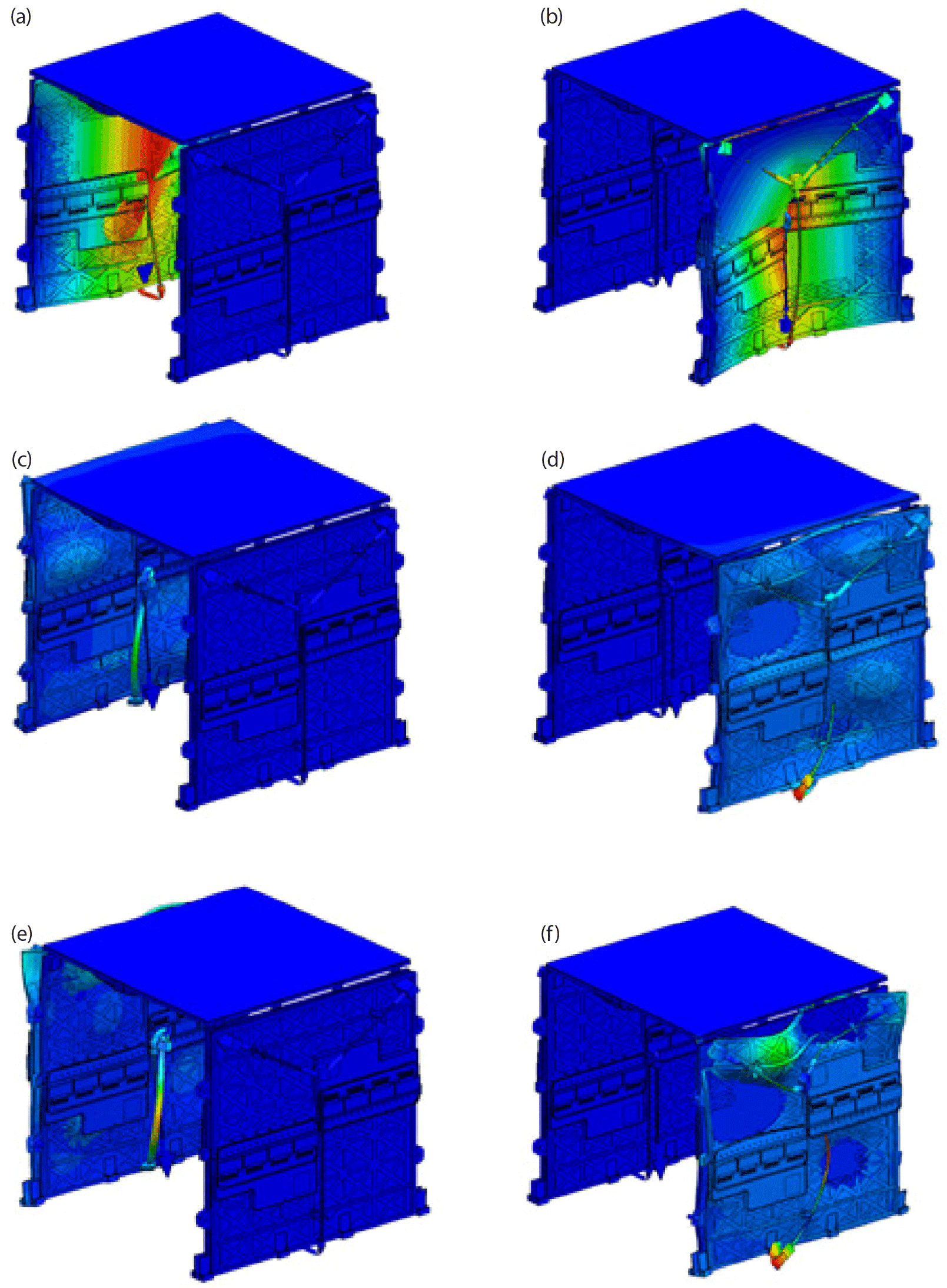
The modal analysis results are shown in Table 2 and Fig. 5. Upon conducting calculations for 200 modes using the Lanczos technique, cumulative fractions of 77.2%, 78.5%, and 93.5% were observed in the respective axial directions. The predominant modes emerged as follows: the 1st and 2nd mode in the X-axis direction, the 57th and 58th mode in the Z-axis direction, and the 62nd and 63rd mode in the Y-axis direction. The 1st fundamental frequency of the antenna is the top and bottom mode of the panel and appeared at about 45 Hz. Due to the similarity in the symmetric configuration, the modes also exhibit symmetry, thus validating the accuracy of the analysis. In this analysis, a value lower than the target value of 45 Hz was obtained for the first natural frequency. To satisfy the target, modal analysis was conducted by modifying the configuration and boundary conditions, resulting in the acquisition of a model with a first mode exceeding 45 Hz. However, in this study, it was determined that a simpler design for lighter weight and ensuring reliability was more important than structural stability, which is why this model was selected. If the first mode requirement in the launch vehicle is above 45 Hz in future cases, the design model obtained through our preliminary analysis can be utilized.
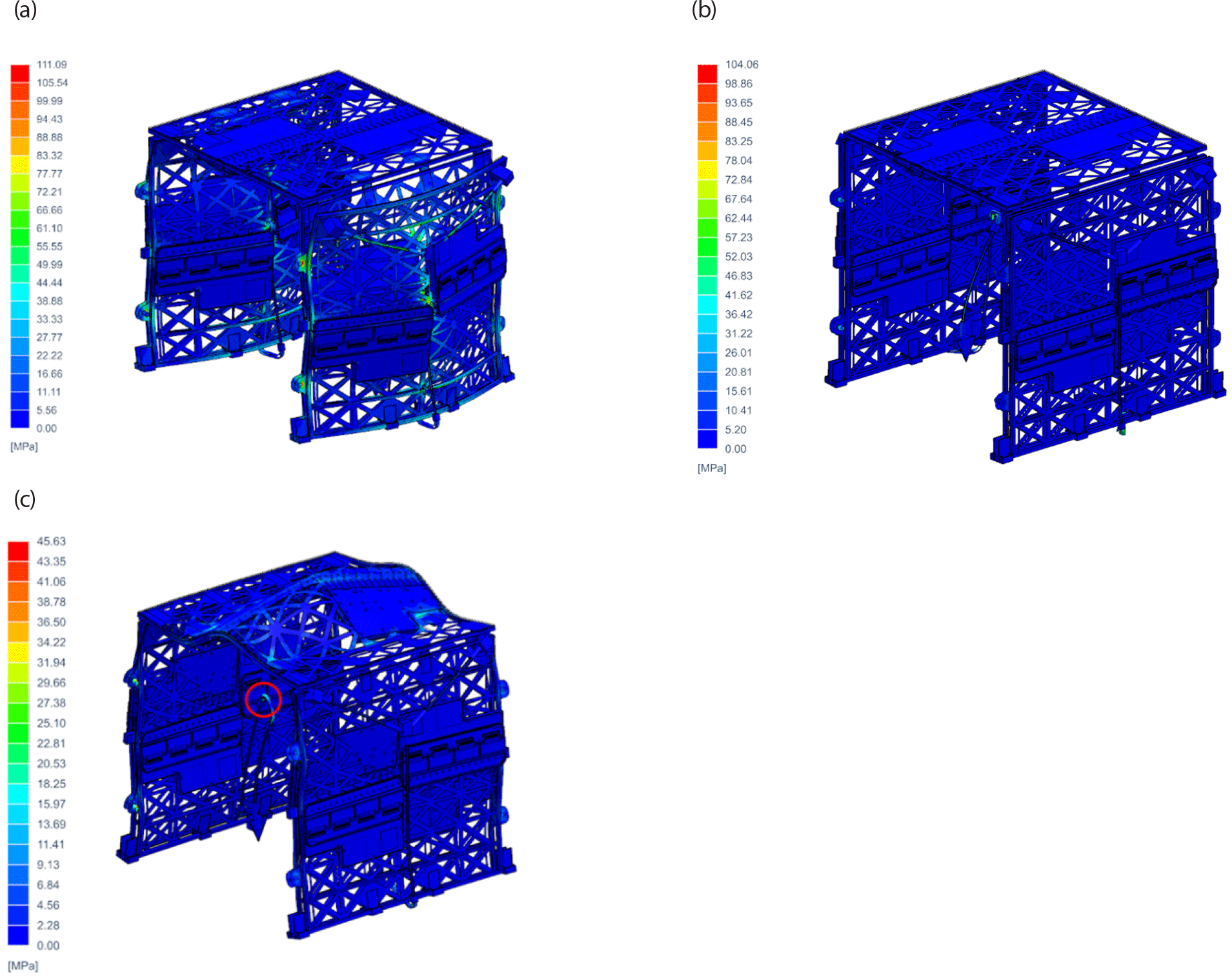
For the analysis conditions, an acceleration of ± 20 g was applied in the X and Y-axis directions (Lateral dir.), respectively, and an acceleration of ± 20 g was applied in the Z-axis direction (Axial dir.). Generally, the load in the axial direction is greater; however, when a satellite is mounted on the launch vehicle in a rideshare or piggyback configuration, it may also be mounted perpendicular to the trajectory of the launch vehicle. In such cases, a greater load acts in the lateral direction. Therefore, we conducted the analysis by applying the worst-case loads provided by the launch vehicle in each axis direction. The maximum stress occurred in the holding device at 111.1 MPa when an acceleration of 20 g was applied to the X-axis. Stress throughout the overall structure, excluding the holding device and struts, remained below 60 MPa, revealing the structural sensitivity to acceleration along the X-axis. The margin of safety for the maximum stresses at each directional singularity ranged from 0.92 to 3.39, indicating a high level of safety in terms of the quasi-static loading condition. Fig. 6 shows the points where the maximum stress occurred from the results of quasi static analysis, and Table 3 shows the margin of safety values at these points.
The random input excitation was set as follows (NASA GSFC 2013; Table 4 and Fig. 7).
| Frequency (Hz) | Acceleration PSD (g2/Hz) |
|---|---|
| 20 | 0.026 |
| 50 | 0.16 |
| 800 | 0.16 |
| 2,000 | 0.026 |
| Overall RMS | 14.1 Grms |
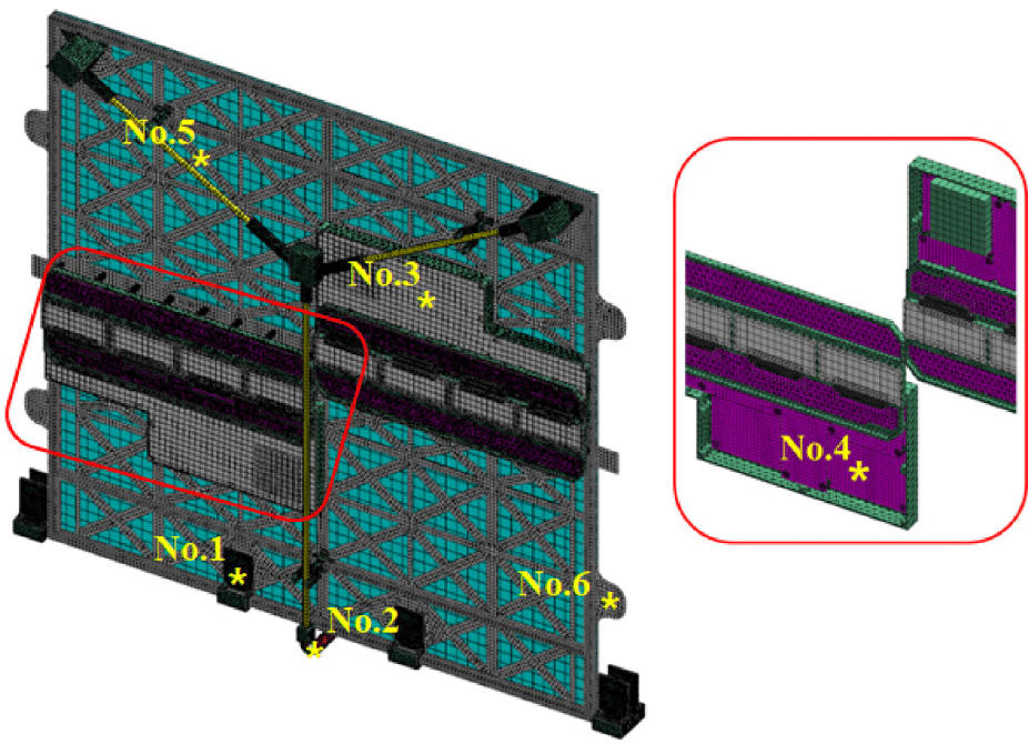
The measurement locations are shown in Fig. 8 as the hinge (No.1), carpenter tape (No.2), TRM electric box housing (No.3) and PCB (No.4), AL structure of the –X-axis direction outer panel (No.5), and the holding device (No.6).
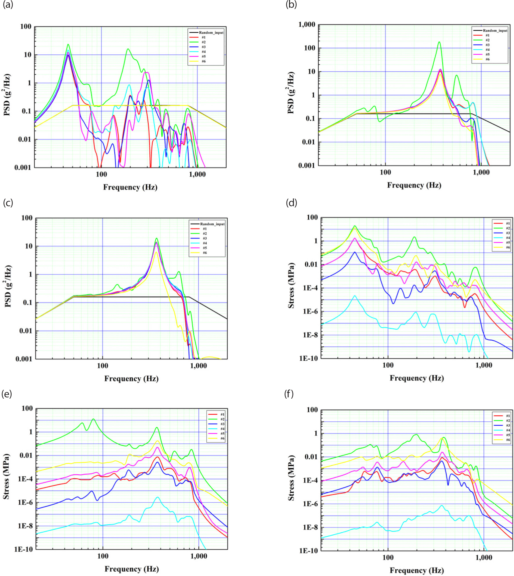
As a result of random vibration analysis, the largest response was found at the carpenter tape (No. 2) for each axial excitation. The level of response to excitation in the X-axis direction is up to 23.7 g2/Hz, receiving a maximum stress of 19.7 MPa from the carpenter tape (No.2), and the level of response to excitation in the Y-axis direction is up to 184 g2/Hz. The carpenter tape (No.2) was found to receive the maximum stress of 13.0 MPa. The level of response to excitation in the Z-axis direction was up to 19.3 g2/Hz, and we confirmed that the carpenter tape (No.2) received a maximum stress of 0.8 MPa. Overall, our model can be considered safe against random vibrations. Fig. 9 shows the acceleration response calculated from the random response analysis.
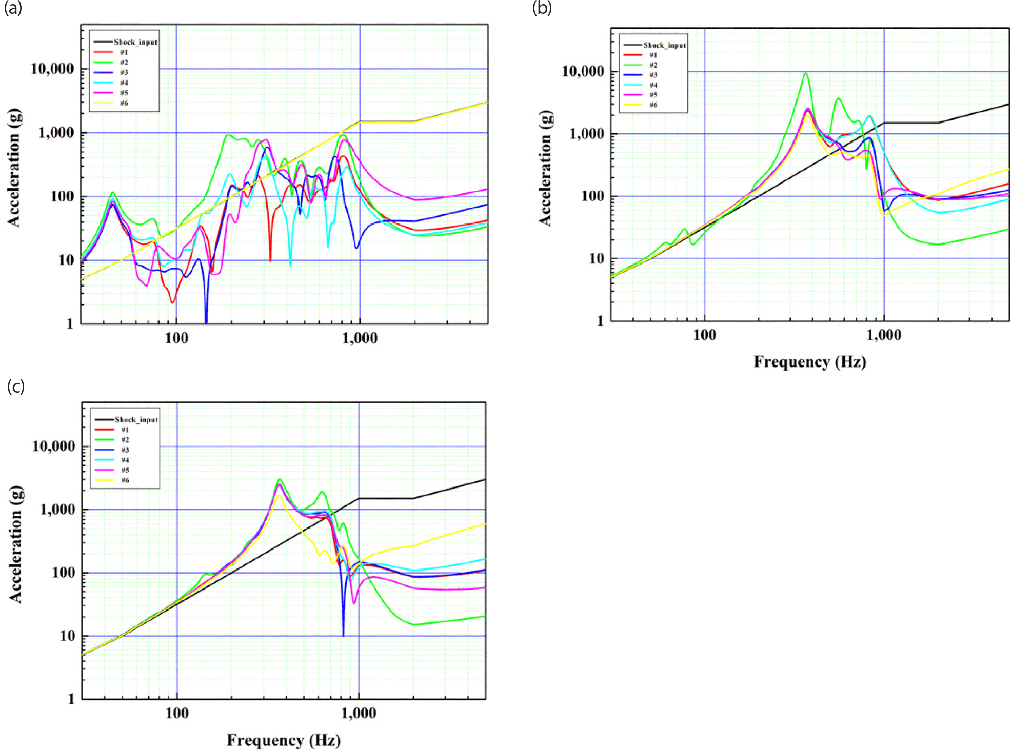
The shock input excitation was set as follows. The shock load is defined at a level that encompasses the shock loads provided by several launch vehicles (Table 5 and Fig. 10).
| Frequency (Hz) | Acceleration (g) |
|---|---|
| 100 | 40 |
| 2,000 | 3,500 |
| 10,000 | 4,500 |
The measurement location is the same as in the random response analysis. The level of response to the acceleration along the Y-axis reaches a maximum of 9,370 g, originating from the holding device and receiving a maximum stress up to 299 MPa. The response in the X-axis was observed at a maximum level of 4,460 g, with stress reaching 64.7 MPa. In the Z-axis, the response level reached a maximum of 3,050 g, with a calculated stress level of up to 433 MPa. Although the stress levels in the Z-axis response do not exceed the yield stress, the Margin of Safety value is calculated to be less than zero, indicating a lack of stability. However, the shock profile set in this analysis simulates the shock generated when the pyrotechnic devices at the interface between the satellite and the launch vehicle explode during satellite separation from the launch vehicle. When conducting satellite payload-level environmental tests, the tests are performed considering the actual levels of shock loads experienced by the satellite payload (Lee et al. 2000). The shock loads transmitted to the payload are attenuated as they pass through the launch vehicle interface, various interfaces, and components after being initiated by the pyrotechnic explosions. Therefore, it is expected that significantly reduced values compared to the shock loads applied in this analysis will be used in actual launch environment testing, indicating that there is sufficient stability in actual testing.
Fig. 11 shows the acceleration response calculated from the shock response analysis.
5. CONCLUSIONS
This paper examined the structural stability of a SAR antenna for a microsatellite. Modal analysis revealed the occurrence of 1st and 2nd modes around 45 Hz, with the dominant mode aligned along the X-axis. The designed antenna satisfies the majority of lateral natural frequencies required by the launch vehicle when piggybacked for launch, ensuring resonance safety with the launch vehicle. A quasi-static load analysis along each axis confirmed margin of safety values exceeding 0.9. Maximum stresses under random vibrations and shock loading were observed near the carpenter hinge and holding device. The safety of our SAR antenna structural design for microsatellites has been established through structural analysis. Future research will involve antenna fabrication and testing to further validate the structural stability of the design.


