1. INTRODUCTION
A CubeSat is a type of miniaturized satellite which is made up of multiple cubes with 10 cm × 10 cm × 10 cm size: one 10 cm edge cube is called 1 U (one unit). The CubeSat program was initiated at Stanford University in 1999 to provide hands-on experience to students on the entire cycle of a space project by developing a low-cost and low-weight satellite. Depending on CubeSat missions, development cost ranges from a few tens of thousands to a few million US dollars by using commercial off-the-shelf (COTS) hardware components, with development time spanning from about one year to a couple of years. So CubeSats are being considered as a competitive solution for space applications because they allow equilibrium among crucial variables of a space project, such as development time, cost, reliability, mission lifetime, and replacement (Villela et al. 2019).
CubeSat class of nanosatellites has received considerable attention for space applications such as education, Earth remote sensing, science, and defense. CubeSat platforms offer opportunities for pathfinder experiments, space qualification of components and systems, and enhancement of larger assets (Rose et al. 2019). But such platform is designed with the size, weight and power (SWaP) constraints in a fast and cost-effective way. Taking advantage of the cubic structure, the solar array mounted on the external structure generates the average power ranging from less than 1 W to 7 W, while the deployable solar array considerably provides 20–60 W in full sunlight (Davoli et al. 2018).
According to nanosatellites database (http://www. nanosats.eu), 1,210 CubeSats had been launched until April 19, 2000, and the most used frequency bands are ultra-high frequency (UHF) occupied by 59.5%, followed by X-band (19.6%) for CubeSat communication systems. The downlink data rate is limited to tens of Kbps due to SWaP constraints for the UHF communication systems onboard CubeSats. It is reported that the maximum data rate achieved was 220 Mbps using an X-band system on a CubeSat, to the ground station antennas with 7 m class diameter reflectors (Devaraj et al. 2017). More power-efficient and higher-rate data downlink capability is required for CubeSats equipping with data-intensive sensors such as hyperspectral imagers or video cameras. The potential of most CubeSat missions is being limited by not only their communication capabilities but also the regulatory issue of licensing the radio frequency (RF) spectrum. The RF spectrum is already very crowded, especially in the lower parts of the spectrum, and getting an allocation from the International Telecommunication Union (ITU) is usually the hardest part of typical CubeSat missions, particularly in the higher RF bands. It can take longer than the CubeSat development time to design, manufacture and test the whole CubeSat, sometimes risking the launch opportunities. With a foreseen increase in the number of CubeSat missions, the current RF spectrum will not be able to support the growing demand for data transmission to the ground (Carrasco-Casado et al. 2017).
An optical communication has been considered as a promising alternative to the RF communications for CubeSats due to the power efficiency and high data rate transmissions as well as the license free spectrum. The first satellite of the optical communication experiment was Fukuoka Institute of Technology SATellite-1 (FITSAT-1), a 1 U CubeSat developed by the Fukuoka Institute of Technology in Japan, which was deployed from the robotic arm of the International Space Station on 2012. The satellite carried two arrays of high-power light-emitting diodes and a passive attitude control system in order to demonstrate a high speed transmitter module (Tanaka et al. 2015). Even though many space missions have launched since FITSAT-1 for optical communication demonstration, there were only two successful CubeSat missions funded by National Aeronautics and Space Administration (NASA) Small Spacecraft Technology Program, AeroCube-7B and 7C known as Optical Communication and Sensor Demonstration (OCSD) satellites. The AeroCube-7A was launched on 2015 with an optical transmitter using a two-stage 10 W Yb fiber master oscillator power amplifier (MOPA) onboard a 1.5 U CubeSat, but the mission was failed due to an unexpected reboot that led to the loss of three-axis attitude control. So two additional 1.5 U CubeSats (AeroCube-7B and 7C) were launched on 2017, and hosted identical single-stage 4 W Yb MOPA optical transmitter to demonstrate downlink rate of 5 to 200 Mbps over a 900 km range (Rose et al. 2019). However, several CubeSat missions are still under development to demonstrate the key components of optical communications for CubeSat-scale satellites, such as the optical-power generation and the pointing capability.
An optical transmitter based on a MOPA architecture is usually limited in peak power, but provides high peak-to-average-power ratio (PAPR) which can improve the average-power efficiency and provide higher modulation bandwidths in the pulse position modulation (PPM). In addition, the MOPA architecture can be not only implemented by using available COTS components but also considered to be suitable for CubeSat SWaP constraints (Kingsbury 2015). In this study, we analyzed the performance of optical downlink channels based on the M-ary PPM in terms of data rate, bit error rate (BER) and outage probability. The log-normal distribution model was used to describe the intensity fluctuations of channel fading by atmospheric turbulence, which is applicable to weak turbulence conditions. Taking into account the log-normal fading channels and a transmitter with a finite extinction ratio, mathematical models of BER and outage probability were derived in terms of the received photon count. First, the optimal guard time and modulation orders were chosen under the condition of fixed slot width, to achieve the target data rate of 100 Mbps. And then two performance metrics, BER and outage data rate, were analyzed and discussed for the chosen modulation orders, with respect to beam divergence angle, scintillation index and zenith angle. Taking into consideration the pointing capability of CubeSat platforms employing closed-loop beacon tracking control, the minimum beam divergence angle and received photon count were also investigated to maintain the reliable optical link even in the presence of weak atmospheric turbulence.
2. SYSTEM AND CHANNEL MODELS
PPM plays an important role in optical communications, particularly in deep space optical communications, because it has attractive properties in terms of average-power efficiency and bandwidth efficiency, and no adaptive threshold is required for detection. PPM is an orthogonal modulation technique, where information is encoded in one of M time slots to denote a binary sequence (or symbol) with log2M bits. A M-ary PPM symbol has exactly one pulse and M-1 empty slots in the frame. This property enables high PAPR even under conditions of very low average power, which makes the M-ary PPM a promising choice for optical communication applications limited by power.
Fig. 1 shows schematic diagram for 4-ary PPM example, where a frame consists of 4 time slots and one guard time. A fixed symbol interval is divided into M time slots (e.g., M = 4 for 4-ary PPM), and the duration of a time slot is called a slot width (Ts). The guard time (Tg) is used not only to prevent back-to-back pulses from hitting the fiber amplifier but also to provide a periodic reference that is helpful for clock recovery (Clements et al. 2016). Taking into account the guard time, the data rate, Rb, for M-ary PPM is expressed as:

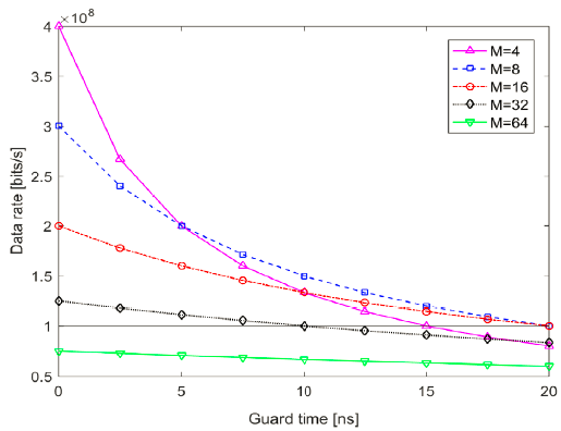
As seen from Eq. (1), longer slot width and longer guard time decrease the data rate of M-ary PPM. So the optimal modulation order can be determined by identifying the M that provides the highest data rate for the given slot width and guard time.
The link equation is a fundamental and useful tool to predict the channel performance of the optical communication system, since it provides a key to the system design and component selection. The link equation represents the relationship between the transmitting optical power (PT) and the received optical power (PR) at the input to the optical detector, and then enables to analyze the trade-offs between system parameters and link performance (Lim et al. 2020a). Taking into account no atmospheric turbulence, the link equation is expressed by:
where ηT is the transmitting optical efficiency, GT and LPT are the gain and the pointing loss of the transmitting telescope, respectively. TA and TC are the one-way transmittances by the atmospheric constituents and cirrus clouds, respectively.
Moreover, ηR is the receiving optical efficiency including the optical filter transmittance, AR is the effective receiving area, and R is the link propagation distance.
By assuming that the transmitting beam has an ideal Gaussian intensity profile, the gain of the transmitting telescope, GT, is given by (Klein & Degnan 1974):
where AT is the effective transmitting area, λ and θDH are the optical wavelength and the far field divergence half-angle of the transmitting beam, respectively. gT is referred to as the transmitter efficiency factor, which is taken as 2 in order to reconcile the link equation with the laser beam propagation equation in terms of spatial domain (Johnson 2009;Lim et al. 2019;Lim et al. 2020b). The pointing loss of the transmitting telescope, LPT, due to the misalignment between the transceivers is described as:
where θE is the beam pointing error.
The one-way atmospheric transmittance, TA and TC, due to the atmospheric constituents and cirrus clouds are expressed as (Degnan 1993;Lim et al. 2020a):
where σ(λ,V,0) and V are the atmospheric attenuation coefficient and the visibility at sea level, respectively. hSH = 1.2 km is the scale height, ζ is the zenith angle of satellite, h0 is the height of optical ground station, and CT is the cirrus cloud thickness.
A major impairment over optical downlinks and uplinks is atmospheric turbulence which causes fluctuations in both intensity and phase of the received signals. Based on scintillation statistics, various fading channel models have been proposed such as log-normal, K channel, Gamma- Gamma, and negative exponential models (Lim et al. 2020a). The log-normal model is suitable for weak turbulence which is characterized by a scintillation index ( ) less than 0.75. If the received intensity is replaced by the average count of received photon (Ks) as a log-normal distributed random variable, the probability density function, f(Ks), is given by (Kiasaleh 2005):
where mk and denote the mean and variance of In(Ks), respectively. These values can be computed by the following equations:
The scintillation index can be expressed in terms of the log-amplitude variance (), commonly referred to as the Rytov parameter. In the case of both weak turbulence condition and downlink, can be written for a plane wave as (Hemmati 2009):
where k is the optical wave number, H is the satellite altitude, and is the refractive index structure parameter.
Many models have been proposed to predict the behavior of refractive index structure parameter. The Hufnagel-Valley model has been widely used for satellite optical communications due to its simplicity and relative accuracy. In addition, it allows an easy variation of the daytime and nighttime profile by varying various site parameters like wind speed, isoplanatic angle and attitude (Kaushal & Kaddoum 2017;Lim et al. 2020a). The model is defined as:
where w and A are the mean square value of the wind speed (in m/s) and the nominal value of the refractive-index structure parameter at the ground (in m-2/3), respectively. It is known that A influences the turbulence strength only near the ground but w influences the turbulence strength in the high altitude, h > 5 km (Shen et al. 2014).
3. PERFORMANCE ANALYSIS
An avalanche photodiode (APD) is widely used in freespace optical communication systems, since it provides a higher sensitivity or responsivity compared to PIN photodiodes and thus improves the system performance (Lim et al. 2020a). By considering the detector noise of the APD and the background noise, electrical signal-to-noise ratio (SNR) of M-ary PPM systems is expressed as (Pham et al. 2014;Kingsbury 2015):
where μ0 and μ1 represent the mean received signals (in amperes) corresponding to the signal and non-signal slots. The mean signal values are defined as:
where P0 and P1 are the received optical power for the signal and non-signal slots, respectively. Pb is the background noise power coming from sky radiance, RD and G are the APD responsivity and gain, q is the electron charge, Ks = RDP0Ts/q is the average received photon count per PPM slot, Kb = RDPbTs/q is the average background-noise photon count per PPM slot. For the M-ary PPM systems employing an average-power-limited transmitter with a finite extinction ratio defined as Rex = P0/P1, the received optical powers in the signal and non-signal slots are given by (Kingsbury 2015):
where PR,avg is the average received optical power which can be computed using the link equation in Eq. (2). Pb is given by (Hemmati 2009):
where Lλ is the sky spectral radiance, ΩFoV is the receiver field of view in steradians, and Δλfilter is the bandwidth.
In Eq. (12), and are the variances of receiver noises including shot noise and thermal noise, corresponding to the signal and non-signal slots. By assuming that the receiver noise is additive Gaussian noise with zero mean and variance, these noise variances are defined as:
where q is the electron charge, F is the APD excess noise factor, is the thermal noise defined as , kB is the Boltzmann constant, T is the absolute temperature, RL is the load resistor of receiver circuit, and Δf is the effective noise bandwidth. For M-ary PPM, Δf is related to the bit rate and modulation order as Δf = MRb/(2 log2M) = 1/ (2Ts) (Pham et al. 2014).
Thus, the instantaneous SNR of Eq. (12), γ(Ks), can be expressed in terms of Ks as:
Symbol errors happen when one of non-signal slots has the highest intensity due to background noise or electronics noise, or when all slots have equal intensity. Denoting Pse as the symbol error probability, the instantaneous BER can be expressed as:
Pse can be computed by applying Boole’s inequality known as the union bound. If Iu is the intensity of slot u and s0 is the transmitted symbol, and we assume that u = 0 is the signal slot, the upper bound to the instantaneous symbol error probability can be expressed as (Pham et al. 2014):
where Q(‧) is the Q-function defined as Q (x) = (1/2)erfc () , and erfc(‧) is the complementary error function.
Taking the intensity scintillation into account, the average BER over log-normal fading channels is expressed as:
where wi and xi denotes the weight factors and the zero points of the nth-order Hermite polynomial, whose values are well tabulated (Ghassemlooy et al. 2019). Eq. (20) can be derived using Craig’s formula, an alternative form of Q-function (Kiasaleh 2005). The order of Hermite polynomial is chosen depending on the desired accuracy, which was taken as 20 in our numerical simulation.
Outage probability (Pout) is a significant metric to evaluate the reliability of fading communication channels, which is defined as the probability when the instantaneous SNR falls below a certain threshold (γth). Pout is related to the receiver’s sensitivity limit, and can be also described in terms of the received photon count. Thus, Pout over the log-normal fading channel is expressed as:
where Ksth is the critical threshold of the received photon count, which is taken as to satisfy the condition of γ(Ksth) = 1 in this study.
4. NUMERICAL RESULTS AND DISCUSSIONS
In this section, we present the numerical results to analyze the performance of M-ary PPM optical downlink communications over log-normal fading channels for a CubeSat platform, in terms of data rate, BER and outage probability. The MOPA architecture was considered in an optical transmitter with a finite extinction ratio, which provides high PAPR but low average transmitting optical power, PT = 200 mW at 1,550 nm wavelength in the simulation. It was assumed that the transmitter clock runs at 800 MHz, generating a fixed slot width (i.e., Ts = 1.25 ns). The Geochang station was also considered as the optical ground station because an optical receiver can be implemented easily on the optical table owing to its novel configuration (Lim et al. 2018), which is located at Mt. Gamak (h0 = 934m) and has a large optical telescope (diameter = 100 cm).
We aim to achieve the target performance (i.e., data rate of 100 Mbps, BER of 1.0 × 10⁻⁴, outage probability of 1.0 × 10⁻⁵) for a CubeSat with 400 km altitude and 70° azimuth angle, under weak turbulence conditions with the scintillation index of . Taking the clear sky and low optical thickness into account, it is assumed that the atmospheric attenuation coefficient and cirrus cloud thickness are σ(λ,V,0) = 0.25 and CT = 700m, respectively. In addition, the spectral radiance of the sky is assumed to be Lλ = 0.015W/ cm2‧ster‧μm at 1,550 nm. Table 1 shows the parameters related to the transmitter and receiver, and used in the numerical simulations.
Given the fixed slot width, the maximum data rate is achievable for the optimal modulation order and guard time using Eq. (1). As shown in Fig. 2, longer guard times make the PPM data rate lower, and the PPM data rate is reduced sharply as the modulation order decreases. But the guard time should be so large enough that the pump power charges a fiber amplifier and allows for the required peak-to-average-power. The modulation order of M=64 cannot exceed the target data rate of 100 Mbps, regardless of guard times. So the optimal (or maximum) guard time was taken as Tg = 10 ns because 4 modulation orders (i.e., M = 4, 8, 16, 32) satisfy the target data rate for the given slot width.
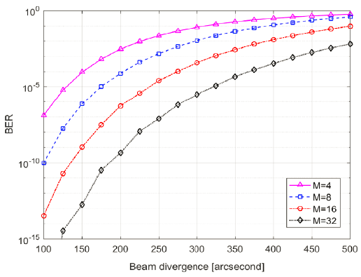
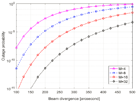
The beam divergence is a major design parameter, which plays a significant role in achieving a reliable communication link over fading channels. It should be determined by considering not only the channel performance but also the CubeSat pointing accuracy. It is known that the CubeSat with 1.5 U and 2.3 kg provided 0.024 deg (86.4″) of pointing error using a star tracker and 3-axis reaction wheels, without beacon tracking (Rose et al. 2019). And the CubeSat designed by COTS components enables the fine tracking accuracy of 0.38 mrad (78.4″) through closed-loop beacon tracking control by a fast steering mirror, without a star tracker (Clements et al. 2016). By assuming that a pointing loss is 3 dB and pointing error is 0.38 mrad achievable by closed-loop beacon tracking control, the required beam divergence is 1.29 mrad (266.7″) from Eq. (4). But a pointahead angle should be also considered in the beam divergence if the transmitter has no point-ahead system, which is a pointing offset caused by a relative motion between the transmitter and the receiver. Taking the point-ahead angle into account, the required minimum beam divergence is 267″ because the point-ahead angle is about 51 μrad for the downlink from low earth orbit satellites.
Fig. 3 and 4 show the channel performance of BER and outage probability for a CubeSat with 400 km altitude and 70° azimuth angle (corresponding to R = 982 km), in the presence of typically weak turbulence of = (A = 1.7 × 10⁻¹⁴m-2/3, w = 21 m/s). Lower modulation order deteriorates the channel performance compared to higher one even though it provides higher data rate. At the minimum beam divergence angle of 267″, the target performance of BER and outage probability is satisfied for two modulation orders (i.e., M = 16, 32). But the beam divergence angle can be allowed up to 275″ and 320″ for M = 16 and M = 32, respectively, because they fulfill three target performance. It is noteworthy that the minimum received photon count (Ksth) should be larger than 145 resulting from the condition of γ(Ksth) = 1, in order to maintain the reliable downlink.
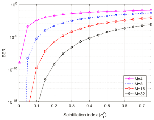
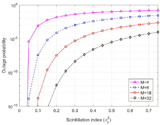
Atmospheric turbulence directly degrades the channel performance, and can even terminate the communication link (Lim et al. 2020a), whose strength is expressed by scintillation index. Therefore, it is essential to analyze the channel performance in terms of scintillation index. Under the condition of fixed beam divergence angle (i.e., 267″), Fig. 5 and 6 show the channel performance of BER and outage probability for the CubeSat at the same location as Fig. 3 and 4, with respect to scintillation index. BER and outage probability are affected more seriously by scintillation index than beam divergence angle, and higher modulation order ensures more reliable communication link over log-normal fading channels. The target performance of BER and outage probability is guaranteed within the common value of weak turbulence for 16 and 32 modulation orders (i.e., for M = 16, and for M = 32). Various techniques have been proposed to mitigate the channel performance degradation due to atmospheric turbulence (i.e., aperture averaging, error control coding, adaptive optics, and spatial diversity), which can be employed for the CubeSat optical downlink.
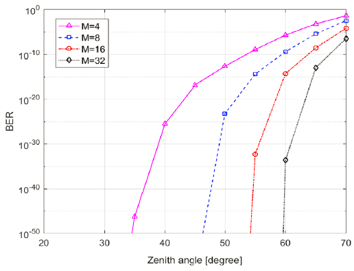
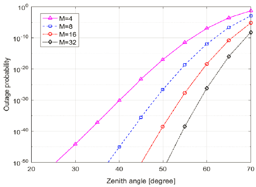
Atmospheric transmittance is dominated by the atmospheric constituents in the region of ζ ≤ 45°, but by cirrus clouds near high zenith angle, which ranges from 0.05 to 0.55 for clear sky and average thickness of cirrus clouds. For the CubeSat orbit with 400 km altitude, the slant range varies from 400 km at ζ = 0° to 982 km at ζ = 70°. In the condition of atmospheric turbulence with A = 1.7 × 10⁻¹⁴ and w = 21 m/s, the scintillation index has a range from at ζ = 0° to at ζ = 70°. These three factors (i.e., atmospheric transmittance, slant range and scintillation index) make a fantastic difference of the channel performance at ζ = 0° and ζ = 70°. Under the condition of fixed beam divergence angle (i.e., 267″) and atmospheric turbulence (A = 1.7 × 10⁻¹⁴m-2/3, w = 21 m/s), Fig. 7 and 8 show the channel performance of BER and outage probability with respect to zenith angle. As expected from the previous statements, the target performance is available in the region of ζ < 60°, regardless of the modulation order. Thus, the channel data rate can be increased by switching the modulation order to lower one while zenith angle is smaller than 60°, guaranteeing two target performance of both BER and outage probability. The transmitter was designed to allow the modulation order to vary between 4 and 64 so that the channel data rate increases significantly from 18.75 Mbps to 100 Mbps (Kingsbury 2015).
5. CONCLUSIONS
An optical communication system onboard CubeSat platforms has gained significant attention, owing to the power efficiency and high data rate as well as the license free spectrum. In this study, we analyzed the performance of M-ary PPM optical communication system for the CubeSat platforms in terms of data rate, BER and outage probability. The transmitter based on a MOPA architecture allows a power-efficient and compact design, and can be implemented by available COTS components that are also compatible with SWaP constraints. The log-normal model was applied to describe the atmospheric turbulence, which is valid only for weak turbulence conditions.
The optimal guard time and modulation orders were selected to achieve the target data rate of 100 Mbps for the fixed slot width of 1.25 ns. It was investigated that the larger modulation order decreases data rate, but improves the communication performance. Considering the closed-loop beacon tracking capability of CubeSat platforms and pointahead angle, the minimum beam divergence angle should be larger than 267″. According to the simulation results, two modulation orders (M = 16, 32) satisfied not only the minimum beam divergence requirement but also the target performance under the conditions of weak turbulence () and low zenith angle (ζ ≤ 70°). Taking the pointing capability of CubeSat platforms into account, the minimum beam divergence angle could be allowed up to 275″ and 320″ for M = 16 and M = 32, respectively. But the target performance is achievable in the region of ζ ≤ 60° for the 4 modulation orders (M = 4, 8, 16, 32) due to better atmospheric transmittance, shorter slant range, and lower scintillation index. Therefore, the channel data rate can be increased by switching the modulation order to lower one in the region of ζ ≤ 60°. It was demonstrated that the minimum received photon count should be larger than 145 corresponding to the receiver sensitivity, in order to make the optical downlink reliable. These simulation results may be contributed in not only deriving requirements but also determining design parameters of an optical communication payload compatible with SWaP constraints. In addition, the mathematical models can be also utilized to predict the payload performance over downlink fading channels in the presence of weak atmospheric turbulence.


