1. INTRODUCTION
Satellite optical communication has received considerable attention as a promising technology for satellite communication, owing to its larger bandwidth, license free spectrum, higher data rate, better security, smaller size, lower mass, and lower power consumption compared to satellite microwave communication (Ma et al. 2015;Kaushal & Kaddoum 2016). Earth observation satellites equipped with high resolution cameras or synthetic aperture radars generate large volumes of data at rates of several Giga-bits per second (Gbps); these performances are required for the transmission of data to the ground with low latency. However, conventional microwave communication makes a bottleneck in transmitting a large volume of data to the ground, because its communication speed is limited to hundreds of Mega-bits per second (Mbps) (Knapek et al. 2007).
In addition, the communication link between a ground station and a low Earth orbit (LEO) satellite is established 6–8 times per day for 5–15 min (Cakaj et al. 2007). To transmit the observation data obtained by LEO satellites to the ground in near real-time, the LEO-to-ground optical communication is required through a geostationary earth orbit (GEO) relay satellite. A general GEO relay system provides an optical communication link between the LEO and GEO satellites, as well as a Ka-band communication link between the GEO satellites and the ground. However, an optical communication link from the GEO satellites to the ground is also required because the Ka-band downlink could become a bottleneck for the whole GEO relay system.
Experiments of satellite optical communication have been performed during many space missions in order to demonstrate and characterize inter-satellite links, downlinks, and uplinks. A first experiment was conducted in 1995 to demonstrate the fundamental technologies for space laser communication between an optical ground station (OGS) and the Japanese engineering test satellite VI (KIKU- 6), which was designed for a geostationary orbit. Recently, the United States, Europe, Japan, and Russia have developed their own optical relay systems using GEO satellites for LEOto- ground communications.
When a laser beam propagates through the atmosphere, its wavefront gets distorted and its spatial and temporal intensities fluctuate due to atmospheric turbulence. This turbulence directly degrades the communication performance of downlinks and uplinks, and can even terminate the communication link. Therefore, for the design of optical uplinks and downlinks, it is essential to know the characteristics of atmospheric beam propagation. Many statistical models have been proposed to describe the atmospheric turbulence channel (e.g., the log-normal, K channel, Gamma-Gamma, and negative exponential models). The log-normal model is applicable only to weak turbulence conditions (Kiasaleh 2005), the K channel model is well suited to stronger turbulence channels (Parry & Puaey 1979), and the Gamma- Gamma model is valid for all turbulence regimes, from weak to strong conditions (Andrews et al. 2001). Many techniques have been also proposed to mitigate the influence of atmospheric turbulence, including aperture averaging, multiple input multiple output, error control coding, adaptive optics, and spatial diversity (Ma et al. 2015).
Currently, the intensity modulation with direct detection (IM/DD) scheme based on on-off keying (OOK) modulation has been widely applied to free space optical (FSO) communication due to the benefits of its simple implementation and its high bandwidth efficiency. The data rate of OOK is hardly over 2.5 Gbps, even though the phase fluctuation effect created by atmospheric turbulences is not noticeable at the bit error rate (BER) performance (Li et al. 2016). Phase modulation schemes (e.g., differential phase shift keying (DPSK) and binary phase shift keying (BPSK)) can provide a better BER performance and a higher data rate than IM/DD schemes, which encode information on their phase but are sensitive to the phase fluctuation effect. DPSK has received significant interest in the field of FSO communication, due to its relatively low power requirements (3 dB less than OOK modulation) and the sensitivity of the DPSK receiver (that approaches the quantum limit theory) (Kaushal & Kaddoum 2016). Contrary to the BPSK, which has to be demodulated using a phase noise compensation technique (e.g., optical phase-looked loop), the DPSK does not need an accurate phase noise estimation; in fact, its demodulator compares the phase changes of two successive symbols, rather than the absolute phases. Thus, the DPSK seems to be a suitable solution for low-complexity and high-data-rate systems when an absolute phase estimation is not feasible (due to the effects of atmospheric turbulence on optical downlink and uplink communication).
Korea plans to develop an experimental GEO relay system that uses an optical communication link to transmit a large amount of data to the ground with low latency; such data would be obtained from a high resolution camera or a synthetic aperture radar onboard LEO satellites. The satellite laser ranging station at Geochang (Lim et al. 2018) can be used as an OGS: it has a novel, effective, and cost-optimized configuration that allows its transformation into a OGS; moreover, it is equipped with adaptive optics that can reduce the influence of atmospheric turbulence. The GEO relay experiment will contribute to implement deep space optical communication for the future planetary missions planned by Korean (Song et al. 2018). In this study, we analyzed the performance of optical inter-satellite links and downlinks in the GEO relay system employing DPSK modulation in terms of link margin, BER, and channel capacity. The link margin is a necessary parameter to consider for the design of a suitable GEO relay system; additionally, both the BER and channel capacity should be analyzed to evaluate the optical channel quality in the presence of atmospheric turbulence. The Gamma-Gamma distribution model was used to describe the intensity fluctuations of the optical beam through the atmospheric media which tend to degrade the performance of the BER and the channel capacity. The channel performance of the inter-satellite link was investigated based on the receiving aperture and the transmitting power, while the channel performance of the downlink was investigated based on both the atmospheric turbulence condition and the transmitting power. Finally, the system parameters (i.e., receiving aperture and transmitting power) were analyzed to achieve the performance criteria of the GEO relay system.
2. SYSTEM AND CHANNEL MODELS
The link budget is a fundamental and useful tool that can be used to predict the channel performance of optical communication systems, since it provides a key to system design and component selection. The link budget represents the relationship between the transmitting power (PT) and the optical power received (PR) at the input to the optical detector, as given by the link equation:
where ηT is the transmitting optical efficiency, while ηA and GT are the aperture illumination efficiency and the gain of the transmitting telescope, respectively. TA and TC are the one-way transmittances given by the atmospheric attenuation and cirrus clouds, respectively; moreover, ηR is the receiving optical efficiency, GR the gain of the receiving telescope, ηfilter the optical filter transmittance to remove background noises, λ the transmitting optical wavelength, and R the link propagation distance. The temporal fluctuations caused by atmospheric turbulence are not explicitly considered in the link equation but should be taken into account for the link margin.
Considering the Gaussian beam mode and the beam pointing error (θE), the transmitting gain is given by (Degnan 1993):
where θD denotes the far field divergence half-angle of the transmitting beam. The one-way transmittance given by the atmospheric attenuation and cirrus clouds can be expressed as (Degnan 1993):
where σ(λ, V, 0) and V are the atmospheric attenuation coefficient and the visibility at sea level, respectively; moreover, hSH = 1.2 km is the scale height, θZ the zenith angle of the satellite, ht the OGS height, and φ the cirrus cloud thickness (mean value = 1.341 km). By neglecting the losses due to the spillover of signal energy beyond the detector perimeter, the gain of the receiving telescope can be described as (Degnan & Klein 1974):
where AR is the effective receiving area of the primary mirror and γ the obscuration ratio of the primary mirror.
Avalanche photodiodes (APDs) are widely used in FSO communication systems, since they provide a higher sensitivity or responsivity compared to PIN photodiodes. In the case of inter-satellite links and GEO downlinks with long beam propagation ranges, APDs is employed to amplify weak receiving signals. By considering the detector noise of the APD and the background noise, the signal-to-noise ratio (SNR) of the DPSK modulation (Li et al. 2016) can be derived to the following expression:
where G is the APD gain, Rd the detector responsibility, Pb the background noise power, Idc the dark current, q the electronic charge, F the excess noise factor, Ts the bit time, κ the Boltzmann’s constant, Te the temperature, and RL the load resistance. The detector responsibility is defined as Rd = ηQq/hv; where ηQ is the quantum efficiency, h the Plank’s constant, and v the optical beam frequency. Moreover, the excess noise fact can be expressed in terms of ionization coefficient ratio (keff) as follows: F = keffG + (1 – keff) (2 – 1/G). The SNR is essential when assessing the optical link performance (e.g., BER and channel capacity).
The background noise results from radiations coming from both the sky and the Sun. The effect of background radiations emitted from celestial bodies (e.g., stars) is negligible in FSO communication, even though they contribute significantly to the background noise in deep space optical communication. The background power collected by the receiver from the sky and Sun is given by (Hemmati 2006):
where Lλ and Iλ are the spectral radiance of the sky and the exo-atmospheric solar constant, respectively; moreover, ΩFoV is the receiver field of view in steradians and Δλfilter the bandwidth of the optical bandpass filter. It is necessary to modify Eq. (8) in order to apply it to both inter-satellite links and downlinks. The solar irradiance reflected by the Earth’s atmosphere needs to be taken into account for the inter-satellite links by applying the Earth albedo (~0.29); additionally, the sunlight passing through the Earth’s atmosphere needs to be considered for the downlink by multiplying the atmospheric attenuation.
An atmospheric channel is under the influence of atmospheric turbulence resulting in intensity fluctuations. Assuming that the fluctuations in optical radiation traversing a turbulent atmosphere consists of small-scale (scattering) and large-scale (refraction) effects, the atmospheric turbulence can be modeled by the Gamma-Gamma distribution (Andrews et al. 2001):
where I and I are the irradiance and the average irradiance, respectively; additionally, Γ(∙) is the gamma function, Km(∙) the m th-order modified Bessel function of the second kind, and α and β represent the effective parameters of large- and small-scale cells under atmospheric conditions, respectively. Assuming a plane wave propagation, the effective parameters are given by:
where is the Rytov variance used to represent the strength of the atmospheric turbulence for slant path optical communications. In the case of weak turbulence, can be defined using the refractive index structure parameter ( (Ma et al. 2015):
where k is the optical wavenumber, ζ the zenith angle, h0 the optical terminal height above the ground, and H the satellite altitude.
Many models have been proposed to predict the behavior of the refractive index structure parameter. The Hufnagel- Valley model has been widely used for satellite optical communications, because it allows an easy variation of the daytime and nighttime profiles and is the most suitable for ground-to-satellite uplinks (Kaushal & Kaddoum 2016). The model is defined as:
where w and A are the mean square value of the wind speed (in m/s) and the nominal value of the refractive-index structure parameter at the ground (in m–2/3), respectively.
3. PERFORMANCE ANALYSIS
The performance of an optical communication system is commonly evaluated in terms of link margin, BER, and channel capacity. The link margin is defined as the ratio of the received signal power to the required signal power (Preq) to achieve a specific BER at a given data rate. It can represented as (Ghoname et al. 2016):
where Nb is the receiver sensitivity (in photons/bit) and Rdata the data rate. The link margin value shows how much margin the system has at a given range to compensate for the scintillation loss, the tracking error, etc.
In the absence of atmospheric turbulence and assuming an additive white Gaussian noise channel, the BER and the maximum achievable data rate (i.e., the channel capacity C) can be expressed as follows, respectively (Zhang et al. 2016):
where erfc(∙) is the complementary error function and B the channel bandwidth. The Shannon-Hartley theorem expressed by Eq. (16) states the theoretical maximum data rate transmissible through a channel with an arbitrarily small BER for an average signal power. Eqs. (15) and (16) are applicable to inter-satellite links in the absence of atmospheric turbulence to conduct a performance analysis of the communication channels. However, the performance of BER and the channel capacity is affected by the intensity fluctuations in the presence of atmospheric turbulence. For the computation of the average BER and channel capacity, we introduced the instantaneous electrical SNR (obtained from Eq. (6)) in terms of received intensity I:
Assuming that the random fluctuations of light radiation traversing the turbulent channel have a Gamma-Gamma distribution (see Eq. (9)), the average BER and channel capacity are given by (Ma et al. 2015, Zhang et al. 2016):
Both Eqs. (18) and (19) were used for the performance analysis of the downlink communication channel under atmospheric turbulence.
4. NUMERICAL RESULTS AND DISCUSSION
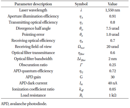
In this section, we present the numerical results obtained for the link margin, BER, and channel capacity, in order to analyze the performance of two optical communication channels for the GEO relay system (i.e., the inter-satellite link (LEO → GEO) and downlink (GEO → OGS) channels). While Eqs. (15) and (16) were used to calculate the BER and perform a channel capacity analysis of the inter-satellite link, Eqs. (18) and (19) were used in the case of the downlink, because its communication channel is affected by atmospheric turbulence. We performed a numerical simulation by considering the target data rate (Rdata) of 1.8 Gbps and propagation distances of 45,000 km and 39,000 km for the inter-satellite link and downlink, respectively. Assuming that the LCT onboard the LEO satellite was the same as that on the GEO satellite, we considered the LCT parameters summarized in Table 1.
The station at Geochang was considered an OGS for downlink communications, equipped with an optical telescope (diameter = 100 cm), having a receiving optical efficiency (ηR) of 0.55, and located at a height (ht) of 934 m. Other optical and electrical parameters related to Geochang station are assumed to be the same as those shown in Table 1. The following parameters were used for the numerical simulation: the zenith angle of the GEO satellite with respect to the Geochang station (θz = 41.3 deg), the atmospheric attenuation coefficient (σ (λ, V, 0) = 0.25), the receiver sensitivity (Nb = 58 photons / bit at BER = 10-9) (Chand et al. 2008), the channel bandwidth (B = 0.9 GHz), the spectral radiance of the sky (Lλ = 0.015 W/cm2sr um), and the exo-atmospheric solar constant (Iλ = 0.027 W/cm2um).
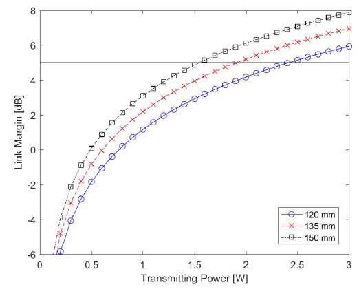
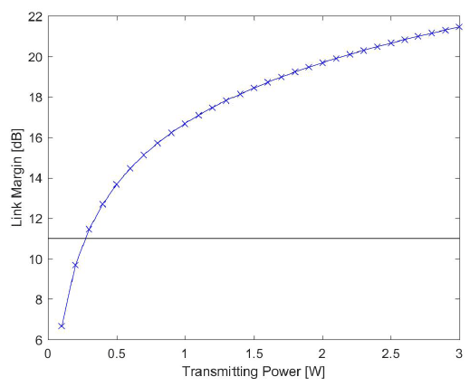
Figs. 1 and 2 show the link margin for the inter-satellite link and the downlink, respectively, in terms of transmitting power. Taking into account unmodeled effects (e.g., phase fluctuations due to atmospheric turbulence) and inaccurate models, we considered a link margin of 5 dB for the inter- satellite link and 11 dB for the downlink: the scintillation loss due to atmospheric turbulence should be considered for optical downlink communications. In general, the scintillation loss can be more than 6 dB and easily exceed 20 dB (Giggenbach & Henniger 2008). According to the link margin results, the design parameter of the transmitting power should be > 1.5 W, 1.9 W, and 2.4 W for receiving apertures of 150 mm, 135 mm, and 120 mm, respectively, in the inter-satellite link; meanwhile it should be > 0.3 W in the downlink. The link margin of the downlink channel is larger than the inter-satellite link under the same transmitting power because the Geochang station was characterized by a much larger receiving aperture.
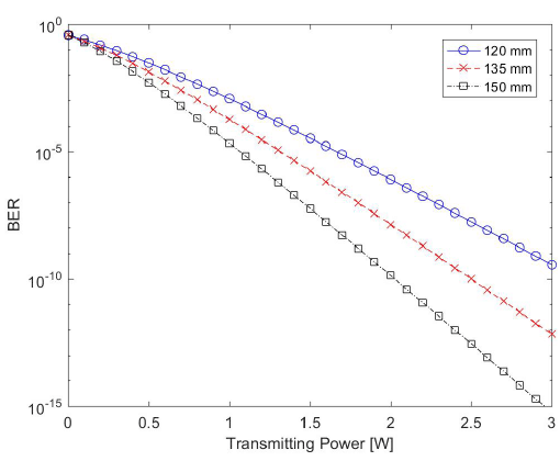
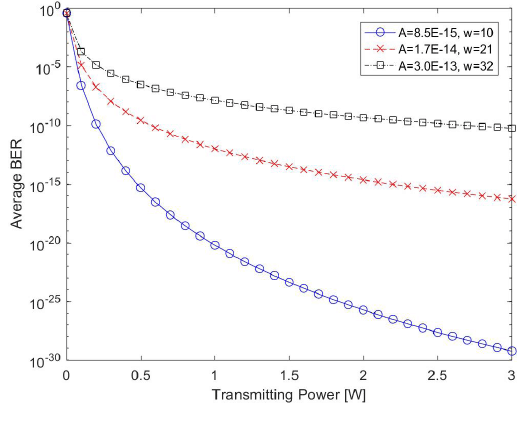
Commonly a BER of 10–9 is required in order to achieve a highly reliable communication over the noise channel. The BER performance of the inter-satellite link in relation to different receiving apertures is shown in Fig. 3. Transmitting powers > 1.8 W, 2.3 W, and 2.9 W are required for receiving apertures of 150 mm, 135 mm, and 120 mm, respectively, in order to achieve a reliable communication. To investigate the BER performance in the presence of atmospheric turbulence, the BER of the downlink channel was evaluated under three turbulence conditions in a weak regime: weak (A = 8.5 × 10⁻¹⁵ m–2/3, w = 10 m/s), moderate (A = 1.7 × 10⁻¹⁴ m–2/3, w = 21 m/s), and strong (A = 3.0 × 10⁻¹³ m–2/3, w = 32 m/s). Fig. 4 shows the average BER of the downlink based on the Gamma-Gamma turbulence model. The most commonly used values are 21 m/s for w and 1.7 × 10⁻¹⁴ m–2/3 for A in the presence of atmospheric turbulence. For the refractive-index structure parameter at the ground, the values of typically range from 10–12 m–2/3 (for strong turbulence) to 10–17 m–2/3 (for weak turbulence) (Ghassemlooy et al. 2013). The required transmitting powers for achieving the target BER (10–9) in the presence of atmospheric turbulence are of 0.2 W, 0.4 W, and 1.7 W for weak, moderate, and strong turbulence, respectively.
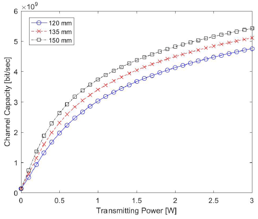
For a given channel bandwidth, the channel capacity depends on the SNR in Eqs. (16) and (19), which means that the highest possible information transmission is achieved at an arbitrarily low error rate. The channel capacity of the inter- satellite link is shown in Fig. 5, while that of the downlink (employing the Gamma-Gamma atmospheric turbulence model) is shown in Fig. 6. In the case of the inter-satellite link, the required transmitting power for achieving the target data rate of 1.8 Gbps is > 0.4 W for the three receiving apertures. As shown in Fig. 6, the average channel capacity of the downlink is not influenced much by the atmospheric turbulence strength, and the required transmitting power is ∼0.1 W at a 1.8 Gbps data rate.
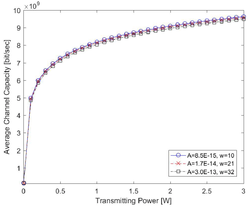
Three criteria were addressed to analyze the performance of the two optical communication channels of the GEO relay system: LM = 5 dB for the inter-satellite link and LM = 11 dB for the downlink, BER = 10–9, and data rate = 1.8 Gbps. In the case of the inter-satellite link channel, the minimum transmitting power of the LCT onboard the LEO satellite required for satisfying the three criteria is of 1.8 W, 2.3 W, and 2.9 W for receiving apertures of 150 mm, 135 mm, and 120 mm, respectively. Regarding the downlink channel, the average channel capacity is hardly influenced by atmospheric turbulence, while the average BER is seriously affected by the turbulence strength. The required transmitting power of the LCT onboard the GEO satellite, in order to meet three criteria even under strong turbulence, is > 1.7 W. Thus, we conclude that minimum transmitting powers of 1.8 W, 2.3 W, and 2.9 W are required for receiving apertures of 150 mm, 135 mm, and 120 mm, respectively, under the assumption that the LEO and GEO satellites are equipped with similar LCTs.
5. CONCLUSIONS
Korea has planned to establish an experimental communication system for LEO-to-ground optical relay link via a GEO satellite. Accordingly, we investigated the performance of the inter-satellite communication link and the downlink employing the DPSK modulation in terms of link margin, BER, and channel capacity. The three criteria of link margin, BER, and data rate can be employed to achieve a reliable optical communication system. The Gamma-Gamma model was used to analyze the performance of the BER and the channel capacity in the downlink channel under atmospheric turbulence which generally causes intensity fluctuations and a degradation of the communication quality.
It was assumed that the two LCTs onboard the LEO and GEO satellites were similar, and that the Geochang station was used as downlink OGS. The performance of the inter-satellite link was investigated in terms of receiving apertures and transmitting power, while the performance of the downlink was analyzed in terms of atmospheric turbulence and transmitting power. We demonstrated that, by taking the atmospheric turbulence conditions into account, the minimum transmitting powers of the LCTs onboard the LEO and GEO satellites should be of 1.8 W, 2.3 W, and 2.9 W for receiving apertures of 150 mm, 135 mm, and 120 mm, respectively. These simulation results may be used in the design of the LCT or, simply contribute to a suitable selection among the LCT products proposed for the Korean optical communication system.


