1. INTRODUCTION
The mission design to place a satellite in an orbit around a celestial body like the Moon is a complex task; hence, it is time-consuming to choose the perfect orbital initial conditions that would meet mission objectives.
Recently, frozen orbits drew particular attention owing to their space-applications like topographic mapping and planetary environment researches and observations. In such orbits, the argument of pericenter and eccentricity are enforced to be stationary by choosing suitable initial conditions, even if the influences of different perturbations are considered.
The history of research on frozen orbits began several years ago, as detailed in a study by Coffey et al. (1994), where many researchers introduced useful contributions. Smith (1986) used Delaunay variables in the canonical formulations of partial derivatives to predict the long-term evolution of eccentricity and the argument of pericenter. Rosborough & Ocampo (1991) utilized Lagrange planetary equations to derive frozen orbits of the Earth using the gravity mode. Lara et al. (1995) used angular momentum polar component to numerically outline families of frozen orbits of the Earth. The same technique was applied to lunar frozen orbits by Elipe & Lara (2003). Aorpimai & Palmer (2003) used epicycle description to compute the Earth’s frozen orbits up to arbitrary zonal harmonics. Zhigang et al. (2014) determined the initial conditions that minimize the variation of the orbital plane for nearly circular orbits with a semi-major axis 3–10 times the Earth’s radius. Santos et al. (2013) searched for frozen orbits through some missions around planetary satellites, like Jupiter’s moons Europa and Icy, and studied their stability. Masoud et al. (2018, 2019) discussed six control strategies to construct artificial frozen orbits and sun-synchronous orbits around the Earth.
Furthermore, solar sail is a modern propulsion method in which the radiation pressure of sunlight is used to propel a spacecraft. It presents long operating lifetimes in addition to low cost of operation. Although its force is lowthrust compared to that of electric engines, it is a perfect continuous force that could be collected over time to be sufficiently large to be considered as a propulsion force. The solar sailing force exerted on an 800 × 800 m2 mirror at one astronomical unit (AU) is about 5 N (Jerome 1992).
Solar sails are applicable to many space missions spread over the entire solar system. Solar sails could reach up to 0.25 AU or even closer to the sun to offer solar observation payloads. They could travel between inner and outer planets. They could also be placed at a stationary point relative to either the Earth or the sun to warn about solar storms (Zubrin et al. 2011). The orbits of Earth’s satellites can be modified by solar sailing. Also, solar sail is suitable for pole sitter and deorbiting (McInnes 2004;Ceriotti & McInnes 2011;Gong et al. 2011;Charlotte et al. 2012).
Wie (2004a, b);Wie & Murphy (2007) studied the solar sail attitude dynamics and how to control it. Cui et al. (2008) derived the dynamical model of multi-body solar sails with control boom. Regarding a low Earth orbit, Polites et al. (2008) presented a numerical simulation on attitude control for a solar sail by using magnetic torquers in addition to small reaction wheels. Liu et al. (2014a, b) presented vibration equations for a solar sail with large flexible established attitude dynamics with control boom, control vanes, and sliding masses.
Carvalho (2016) found the frozen orbits for an artificial Mercuian solar sail considering Mercury’s non-sphericity caused by the zonal terms J2, and J3, solar radiation pressure (SRP), and the sun as a third-body.
Carvalho et al. (2012a,b, 2013) in consequent studies found f Jupiter’s moon (Europa) by, considering Jupiter as a third-body using Lie-transform as an average method within Hamiltonian framework. Abd El-Salam (2013) considered the Poynting–Robertson drag effects of solar sail. In heliocentric orbit, he obtained constraints for solar sail optimal dynamics.
This investigation aimed to determine the frozen orbits around the Moon using continuous acceleration by solar propulsion considering the uneven mass distribution and third body attraction, with the solar sailing as a perturbation force.
The gravitational potential of the Moon is quite different from that of the Earth, so that the zonal harmonics up to J5, first sectorial harmonic C22 and first tesseral harmonic C31 are of the same order (Rahoma 2014;Rahoma & Abd El- Salam 2014).
2. DYNAMICAL MODEL
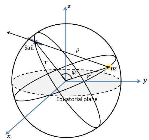
The present dynamical system comprised three bodies: the central body— the Moon, the solar sail spacecraft, and the third disturbing body (TB), with masses m0, m, and m’, respectively. The reference frame Oxyz originated at the Moon and the xy-plane coincided with the lunar equator. The x-axis was along the intersection point between the lunar equator and the TB orbital plane. To define the sail orbits around the Moon, we used the classical Keplerian elements: a, orbital semi-major axis; e, eccentricity; i, inclination; ω, argument of pericenter; Ω, longitude of ascending node; and f, the true anomaly. Further, n refers to the mean motion, where n2a3 = Gm0 with G as the gravitational constant. The TB, m’, is assumed to move in an elliptic inclined orbit around the central body with the orbital elements (a’, e’, i’, ω’, Ω’), and its mean motion n’ is given by n’2a’3 = G(m0 + m’), with the reference frame definition, Ω’ = 0.
Considering the perturbing accelerations, the solar sail equation of motion around the Moon is described by
where is the gravitational acceleration induced by the lunar gravity field, is the acceleration due to the presence of TB, and is the acceleration due to SRP.
The lunar gravity can be written as gradient of the potential UM:
where the quantities Cnm and Snm are the lunar harmonics coefficients. μ and RM are gravitational parameter and lunar equatorial radius, respectively. The quantities (r, λ, φ) are the spherical coordinates of the sail-craft. Further, are the associated Legendre polynomials.
The Moon’s gravity field is rather asymmetric, unlike that of the Earth, where the sectorial coefficient P22 and the tesseral coefficient P31 are larger than the zonal coefficients P2, P3, P4 and P5; thus, P22 and P31 cannot be ignored.
The following equations were derived based on the assumptions of Giacaglia et al. (1970):
where we consider only the harmonics coefficients J2, J3, J4, J5, C22 and C31 (Rahoma 2014;Rahoma & Abd El-Salam 2014).
Also, ζ = cosω cosΩ - cosi sinω sinΩ, χ = -sinω cosΩ - cosi cosω sinΩ.
Using Ψ = a/r, the lunar potential can be rewritten as El-Saftawy (1991)
where
where μM and RM are the lunar gravitational parameter and lunar equatorial radius, respectively, , C = cosi and S = sini
The acceleration vector due to TB (Sun) is
where ' r′ is the solar position vector with respect to the Moon. The quantity μ′ is the solar gravitational parameter. The acceleration can be read as
which may be written as up to the second order
where ψ defines the angle between and '.
Also ψ can be formulated using the orbital elements as follows:
with the following non-vanishing coefficients of Aij (Rahoma, 2016).
Assuming the solar radiation acceleration () and Sun–sail direction are perpendicular to the direction of motion (Fig. 1), the sail acceleration equals the Sun attraction in magnitude, but in an opposite direction.

Solar sailing is a new technology applied in the propulsion of a spacecraft. The reflective surface utilizes SRP to accelerate the spacecraft, consistent with the strategy adopted for IKAROS (2010), NanoSail-D (2010), and LightSail-1 (2016). The sail acceleration is unlimited and continuous, which helps a long term mission. The sailing efficiency depends mainly on the sail lightness number and orientation.
Lightness number, β, is a dimensionless number, and it can be defined as the ratio of acceleration due to solar radiation to acceleration due to solar gravitational pull (Fu et al. 2016).
where ρ is the distance between the sail and the Sun, A is the area of the sail, Pmax(ρ) is the maximum of SRP. It depends on orientation and reflected properties of the sail.
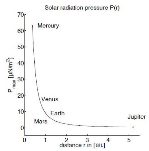
Fig. 2 introduces the values of Pmax which reaches the first five planets in the solar system. On Earth, Pmax is approximately 9 μN/m2.

In other words, the lightness number reflects the ability of the sail to exploit SRP, irrespective of the sail’s size.
Table 1 shows the lightness number, area-to-mass ratio and the featured acceleration for a sail of mass 10 kg (Farres 2019).

|
The acceleration represents SRP due to the Sun and can be written as the equation given by Tresaco et al. (2016).
Using Legendre polynomials to expand equation (6), it returns to the second order as follows:
3. REDUCED SYSTEM
To reduce the dynamical system’s degrees of freedom and eliminate the short-period terms, we present a double- averaging to terminate the short period of the sail and that of TB. The double-averaging for a function F is defined as follows:
Consistent with the derivations provided by Abd El-Salam et al. (2006), the average procedure on the lunar disturbing potential (wherein the orbital elements, except the mean anomaly, are constants) returns the following:
with
where
Averaging over the TB period yields the following (Rahoma 2016):
where the non-vanishing coefficients are as follows:
Averaging Eq. (7) upon the spacecraft’s eccentric anomaly yields
4. COMPUTATION OF FROZEN ORBITS
To formulate the time derivative of pericenter argument and eccentricity, Lagrange planetary equations introduced by Brouwer & Clemence (1961) yields:
Frozen orbit can be guaranteed by elimination of the rate of change of pericenter argument and eccentricity of the orbit, which are referred to as the equilibrium points in the dynamical system:
This procedure is essentially dependent on the effect of the zonal harmonics terms.
Eq. (11) depends mainly on the orbital semi-major axis, eccentricity, and inclination. Therefore, this equation can be represented by a 3D surface (a, e, i) . Each point on that surface represents initial conditions of the frozen orbits.
5. RESULTS AND ANALYSIS
In general, assume that the reference frame had its x-axis coincide with the TB nodal line at the initial time point, i.e., Ω′ = 0, ω = π/2 or 3π/2, and Ω - Ω′= 2kπ, where k is an integer.
Consistent with the findings by Meyer at al. (1994), the required data and orbital parameters of the Moon’s referenced orbit applied in simulation for frozen orbits are mentioned in Table 2.
To derive the lunar frozen orbits, we used equation (13) in equation (11) to yield a solution dependent on (a, e, i), which provided a 3D surface as shown in Figs. 3 and 4.
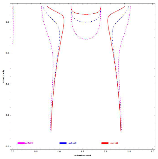
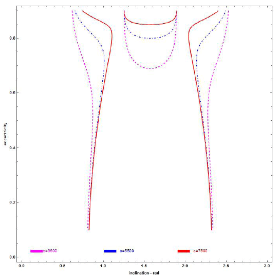
To perform detailed analyses, we presented cross sections at different values for semi-major axis and graph for the entire potential range of the eccentricity and inclination values, i.e., the initial conditions (e, i) of the frozen orbits were depicted for different values of α and β.
Figs. 5 and 6 represent the section (e, i) at β = 0.2 for chosen semi-major (a) 3,500, 5,500, and 7,500 km; ω = 3π/2 and π/2, respectively.


Figs. 7 and 8 show the sections when β = 0.2, 0.8 for α = 2,580 km, and ω = π/2, 3π/2, respectively.
From the graphs, we can observe the following:
1- The eccentricity value of frozen orbits increases when the inclination (i) changes from 0 to π and approaches the families of critical inclinations (inclinations at which apocenter drift is zero) (Rahoma & Abd El- Salam 2014).
2- The effects due to SRP and TB increase with the increase in the orbital semi-major axis; refer Figs. 7 and 8.
3- SRP perturbation is primarily based on the sail’s areato- mass ratio, which is expressed in the dynamic model within β in addition to the orbit semi-major axis.
4- At polar orbits, the eccentricity value of the frozen orbits increases as β increases.
5- Although there are different initial conditions, we observed from the 2D Figs. 5 and 6 that the frozen orbits are nearly the same at ω = π/2 and ω = 3π/2, except for the few dashed lines added to the left-hand side of the figures when ω = π/2.
6- We noticed a significant change in Figs. 7 and 8 depending on the different values for lightness number of the sail, β.
6. CONCLUSIONS
A good understanding of non-integrable dynamics is essential for deriving the locations of the frozen orbits and designing future Moon missions; furthermore, for Moon missions, if we select one parameter of a frozen orbit, we can obtain the remaining two parameters.
The dynamics of frozen orbits of a solar sail planet’s orbiter type has been introduced (applied here to the Moon). The model includes first order of the gravitational sectorial and tesseral harmonics, which in case of bodies like the Moon are sufficiently big and cannot be neglected. These harmonics are considered to be of the same order as that of the zonal harmonics up to J5. Additionally, the model involves TB attraction and SRP. By performing double-average techniques, the short-period terms are eliminated. The study included the third-body’s inclination and eccentricity, which gives an additional complexity to the dynamical equations. In such scenarios, the initial conditions of the frozen orbits are introduced.
A 3D surface was derived where each point represented the initial conditions for lunar uneven mass associated with the chosen frozen orbits, considering different perturbations in formulation equations (11 and 12) of the dynamic model. The sail’s area-to-mass ratio (A/m) has a strong effect on sail-craft dynamics, given the lightness number value, i.e., area-to-mass ratio for the solar sail must be well-planned for future missions. In the future, we aim to extend this study to include effects of the Moon’s gravitational higher harmonics in the dynamics. Also, the attraction of both the Sun and Earth can be enforced in calculations.


