1. INTRODUCTION
The Moon, with its unique geological features and history, offers valuable insights into planetary formation and evolution. Among the various scientific mission objectives, lunar magnetism is one of the key exploration targets that has been investigated since the first lunar survey by Luna 1. Investigating lunar magnetism helps us understand the Moon’s geological history, internal structure, and whether it has a magnetic field generated by a molten core. It also reveals information about the composition of the Moon’s crust and its interaction with solar and cosmic radiation, aiding in comparative studies of planetary magnetism. For these reasons, the magnetic fields of the Moon are continuously observed on the lunar surface and in orbit.
The lunar surface magnetic field has been investigated using two methods: orbiters and landers/rovers. The advantage of using lunar orbiters is that they allow the investigation into the magnetic field of the entire Moon. According to data from previous missions, the Moon does not possess a strong global dipole field, unlike the Earth (Dolginov et al. 1966; Sonett et al. 1967). The lunar surface magnetic field strength was estimated to range from a few to several hundred nanoteslas (nT) (Halekas et al. 2001; Tsunakawa et al. 2015).
In contrast to orbiters, lander- and rover-based magnetic field surveys provide direct measurements of the surface magnetic field and external field variation in specific local areas. Representatively, Apollo 12, 14, 15, and 16 included magnetometers (NASA 1970, 1971, 1972a, 1972b). In particular, the surface magnetic fields across various regions could be measured using the lunar rover on Apollo 16. Through the surveys, it was found that the lunar surface magnetic field does not have a regular directional pattern and distribution, and its maximum field strength was approximately several hundred nT (NASA 1970, 1971, 1972a, 1972b).
The Korean space exploration program has experience with lunar magnetic field measurements by the Korea Pathfinder Lunar Orbiter (KPLO). KPLO is equipped with the KPLO magnetometer (KMAG) to investigate the magnetic field at its orbit. The specification is designed based on a 100 km altitude magnetic field environment (Richmond & Hood 2008): its resolution is 0.2 nT and its measurement range is ± 1,000 nT (Lee et al. 2021).
After the KPLO mission, the Korea Astronomy and Space Science Institute (KASI) has been developing a lunar lander deployable instrument for the Commercial Lunar Payload Service (CLPS) and Artemis program, including the Korean lunar lander mission. Following the KASI’s lunar exploration plan, the lunar surface magnetometer (LSMAG) was developed as one of the candidate payloads. This is one of four Korean candidate payloads for the CLPS program managed by an international collaboration between the KASI and NASA. The LSMAG, based on the design of the KMAG, was improved and redesigned to suit the lunar surface environment and lander platform instead of the orbiter. Its fluxgate magnetometers (FGMs) have a resolution of 0.2 nT and measurement range of ± 2,000 nT.
In the case of lunar surface magnetic field measurements, auxiliary devices are required along with FGMs to acquire their own attitude information, deal with the potential presence of unexpected strong magnetic fields, and detect artificial magnetic field noise. To address these requirements, we developed an independent small module that uses anisotropic magnetoresistive (AMR) sensors in addition to FGM. The mission-assisting anisotropic magnetoresistive sensor (MAMS) modules, which were developed to control AMR sensors and generate the information needed for LSMAG’s mission, were installed in the boom, similar to FGMs.
The strengths of AMR sensors include their effectiveness in measuring strong magnetic fields and their heritage. Typically, they have a measurement range of a few nanoteslas to several millitesla (Lenz 1990), which is wider than that of FGMs. Multiple space missions have utilized AMR sensors. For example, HokieSat (USA) used the HMC2003 sensor (Makovec et al. 2001) and CINEMA (Korea, USA, and UK) used HMC1001 sensors (Brown et al. 2014) to measure the geomagnetic field. KMAG also used HMC1053 to detect large internal magnetic noise (Lee et al. 2023). Because of their proven effectiveness in strong magnetic fields, AMR sensors are suitable to help LSMAG maintain its mission under unexpectedly strong magnetic fields.
In addition to addressing unexpectedly strong magnetic fields, the MAMS module can assist in magnetic field data calibration (noise removal and offset determination) using AMR sensors.
Unlike many space magnetometers with a long boom, such as the Lunar Prospector (LP) with a 3.6 m boom (Binder 1998) or Kaguya with a 12 m boom (Kato et al. 2010), the length of the LSMAG boom is only 1 m because of its size limitation. Referring to the magnetic cleanliness analysis of KMAG which had a 1.2 m boom (Park et al. 2022), a 1 m boom is not sufficient to distance the magnetometers from the lander and reduce the lander-generated magnetic interference. Therefore, the LSMAG is required to utilize multiple sensors, including AMR sensors, to eliminate this interference.
Among the various multisensing techniques, Lee et al. (2023) utilized the AMR sensor of KMAG and FGMs. The wide measurement range of the AMR sensor helped remove spike-like noise from the FGM data. This suggests that adopting the AMR sensor which has different measurement range from that of the FGMs is effective for noise removal. We can expect the MAMS module to assist in removing noise from the LSMAG data, as in the KMAG case.
The MAMS module has another device that assists with data calibration: an offset calibration coil.
The offset determination is critical in data calibration because the failure to do so causes erroneous data fluctuations after the coordinate transformation. There are various offset determination methods for space magnetometers, most of which utilize variations in the interplanetary magnetic field and solar wind (Belcher 1973; Hedgecock 1975; Plaschke & Narita 2016; Wang & Pan 2021). However, these methods are effective only when the magnetic field fluctuates over a certain strength, but can be ineffective for the lander.
The MAMS module overcomes this limitation by driving the coil to generate an artificial magnetic pulse. Because the artificial pulse is an already-known signal, we can determine the offset of the magnetometers from the detected pulse. This method is simple and does not require any specific conditions. This supplements previous offset determination methods that may be ineffective for the lander.
The MAMS module is equipped with an accelerometer to acquire attitude information. This measures the attitude of the LSMAG boom and is useful in interpreting the direction of the magnetic field. This information is typically inferred from the attitude of the spacecraft. However, with the accelerometer of the MAMS module, the LSMAG can obtain more accurate information because the accelerometer directly measures the attitude independently of the lander. In addition, in the case of a malfunction in the lander navigation system, this information can support the lander.
This paper describes the development and performance evaluation of the MAMS module. Section 2 details the MAMS module and its components. Section 3 covers the various tests conducted to verify the actual MAMS module flight model. Section 4 summarizes the results and outlines future plans.
2. THE MISSION-ASSISTING ANISOTROPIC MAGNETORESISTIVE SENSOR (MAMS) MODULE
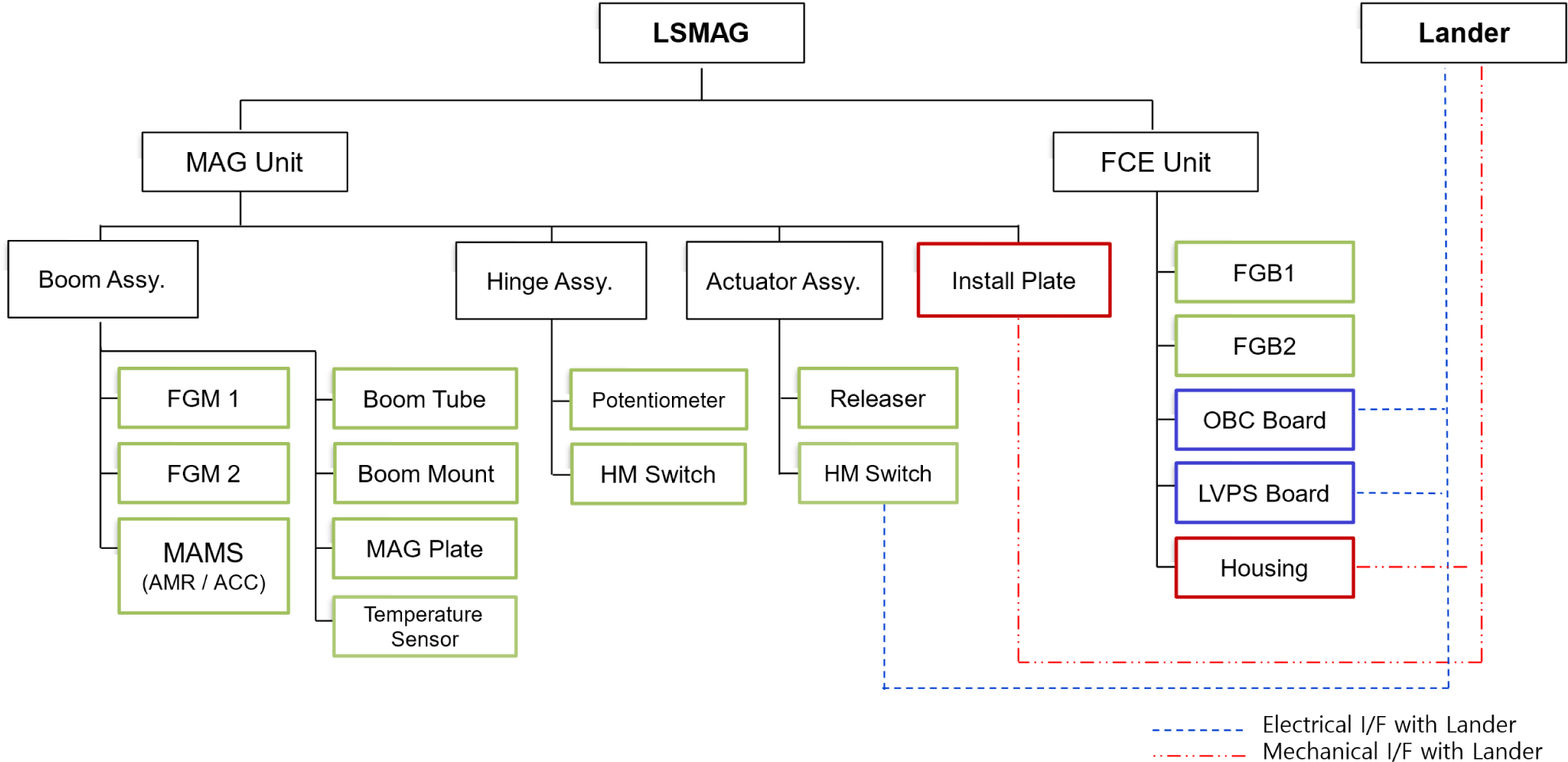
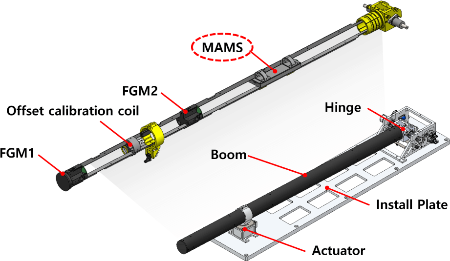
The LSMAG is a deployable lunar surface payload instrument that measures the magnetic fields on the lunar surface. It consists of a MAG unit that includes a hinge, actuator, and boom assembly including an install plate and a fluxgate control electronics (FCE) unit, which controls the LSMAG instrument, power management, and communication. The system configuration is depicted on Fig. 1.
The MAG unit has a hinge assembly, an actuator assembly, and a boom assembly where the sensors are installed (Fig. 2). Two FGMs were installed far from the lander to minimize the artificial magnetic noise. The MAMS module was also installed in the boom assembly but near the lander. Therefore, the module can effectively measure the magnetic noise from the lander and provide noise data.
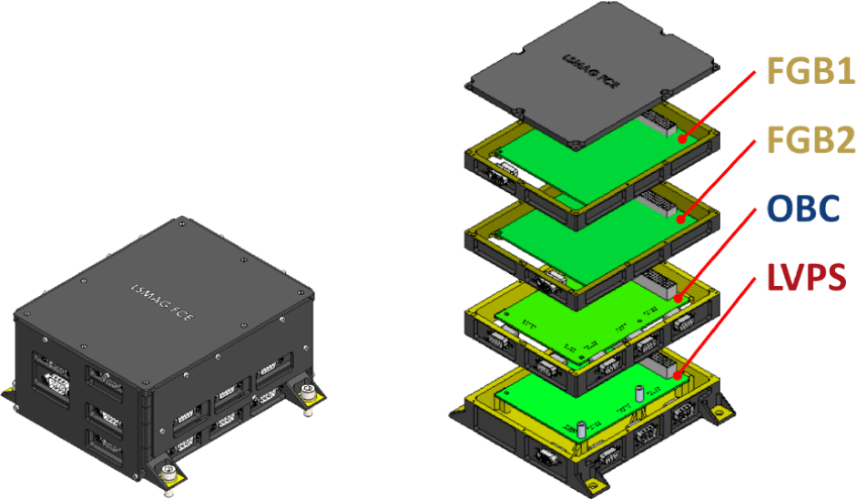
The FCE unit consists of four layers (Fig. 3): a low-voltage power supply (LVPS) board, an OnBoard computer (OBC) board, and two fluxgate magnetometer boards (FGBs). The LVPS can receive unregulated input power ranging from 24 V to 32 V, and converts it to the required voltages (e.g., 3.3, 5, 12 V) to supply power to the LSMAG system. The OBC controls the LSMAG system, communicates with the external module, and processes and stores data from the system. The FGB manages the FGM operation and generates a digital magnetic field dataset. As one FGB is assigned to each FGM, a total of two FGBs are present. Under the command of the OBC, the FGB triggers the FGMs measurement, converts the incoming analog signals into digital data, and transmits the data to the OBC.
The MAMS module is directly connected to the OBC. The module operates and transmits data to the OBC based on its commands. The power of the MAMS module is supplied from the OBC 9 V power path.
The MAMS module is designed to detect unexpectedly strong magnetic fields over the FGM measurement range using AMR sensors, which can sense a wider measurement range than FGMs. Even if the magnetic field at the landing site is weak, the module has the technical objective of providing data on the magnetic interference from the lander. In addition, the module has an accelerometer to measure the attitude of LSMAG’s boom, which provides data that can be used for correction. The MAMS module communicates with the OBC via an RS-485 interface to receive commands and transmit data. The requirements for the MAMS module are listed in Table 1. The requirements of the accelerometer took the difference between the Moon and Earth into consideration.
| Sensor | List | Requirement |
|---|---|---|
| AMR | Measurable range | ± 80,000 nT |
| Resolution | < 20 nT | |
| Noise level | < 5 nT/√Hz | |
| Accelerometer (at the Earth) | Measurable range | ± 2 g |
| Resolution | < 6,000 μg | |
| Noise level | < 400 μg/√Hz |
The MAMS module uses HMC1001/1002 AMR sensors (Honeywell, Charlotte, NC, USA). It has a thin film made of nickel-iron permalloy arranged in a barber-pole structure. Four barber-pole segments form a Wheatstone bridge, and the voltage difference across the bridge is used for estimating the magnetic field strength across the sensor (Honeywell 2019). Notably, the HMC1001 sensor was previously utilized in the CINEMA mission (Brown et al. 2014).
When an external magnetic field is applied, the direction of magnetization of the sensor material changes, which in turn changes the resistivity of the material. This is known as the magnetoresistive effect, which is utilized by AMR sensors to determine the strength of the applied magnetic field.
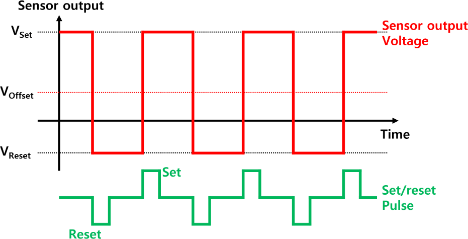
However, the magnetization direction of the material may not return to its original state after exposure to an external magnetic field. This necessitates magnetization realignment for accurate measurements. The HMC1001/1002 sensors perform this realignment using a set/reset strap that generates a magnetic field within the sensor through the brief application of a strong current pulse (Fig. 4). The magnetization direction of the sensor material can be realigned or flipped, depending on the direction of the generated magnetic pulse. When the magnetization direction is flipped, the polarity of the output voltage changes, and the sensor’s offset can be determined from this difference.
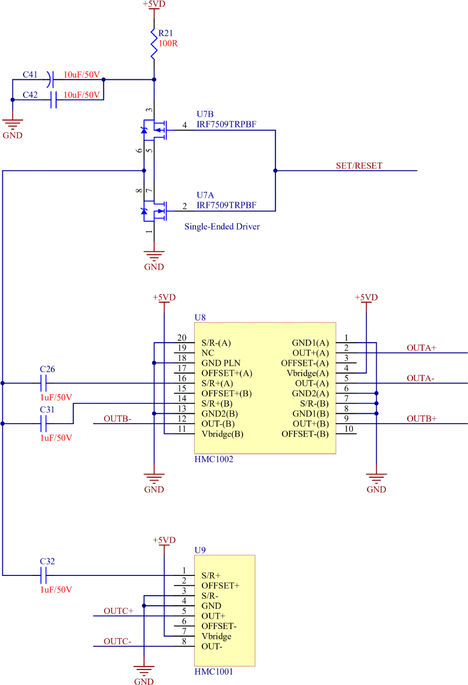
To supply the current for the set/reset operation, we designed a driving circuit (Fig. 5) based on the sample circuit provided by Honeywell (2019). This includes a metal-oxide-semiconductor field-effect transistor (MOSFET) driver and capacitors. The MOSFET driver operates as a switch, and the capacitors are used to supply a large current. This circuit prevents the continuous flow of large currents that could destroy the circuit. The voltage of the node to which the U7A and U7B drains are connected changes sharply depending on the set/reset digital signal (low and high). This generates a voltage pulse across set/reset straps (between S/R+ and S/R-) of each sensor, causing the corresponding current to flow through the set/reset straps. The current decays according to the RC component of the circuit; when the current becomes zero, set or reset is performed. Then, the magnetic field applied to the sensor can be measured.
To digitize the AMR sensor signal, we utilized the internal analog-to-digital converter (ADC) of MSP430i2040, which is a microcontroller unit (MCU) of the MAMS module. It has a maximum 24-bit resolution; however, considering the increasing noise with higher resolution, we set the ADC resolution to 17 bits. It operates in bipolar mode and can read signals within the ±1.5 V range. Because the direct output signal of the sensor is very small (160 nV/nT), it is amplified 50 times using a pre-amp circuit. Although the ADC module can read a negative voltage signal, the amplifier cannot process it. Instead, it becomes saturated because of the absence of a negative voltage in the MAMS module. This causes the negative output of the sensors to become invalid. Therefore, we added a 0.75 V offset to the sensor output during amplification to ensure proper signal processing.
The MAMS module has an accelerometer ADXL355. It has four internal ADCs. Three 20-bit ADCs digitize the applied acceleration along each axis and a 12-bit ADC digitizes the sensor temperature. It is connected with the module’s MCU via a serial peripheral interface to receive the commands and transmit the data. This accelerometer performs two functions: generating attitude information of the LSMAG boom and detecting vibrations.
Generating the attitude information of the LSMAG boom is important to determine the direction of the magnetic field. While the orientation of the boom can be inferred to some extent from the changes in the magnetic field measured by the magnetometer during the deployment phase, the attitude information provided by the MAMS module offers a more direct and accurate measurement of the boom’s position, even under static conditions. Additionally, this information can be used to determine the lander’s orientation. Because the installation positions of the LSMAG on the lander and the MAMS module within the LSMAG boom are known in advance, the relative position between the LSMAG and lander can be determined by reading the potentiometer from the hinge section of the LSMAG. The attitude of the lander can be calculated by transforming the coordinates based on this relative position. If the lander’s navigation system encounters issues, the attitude data measured by the MAMS module can serve as a backup.
During the mission, various components generate vibrations. This can cause fluctuations in the sensor data, which must be eliminated to ensure accurate measurements. By utilizing the system vibration data measured by the accelerometer, the magnetometer and other payloads can obtain more precise measurements. In addition, the accelerometer can detect moonquakes with a magnitude of 1.7 or higher; some shallow moonquakes are known to occur within this range (Nakamura et al. 1979).
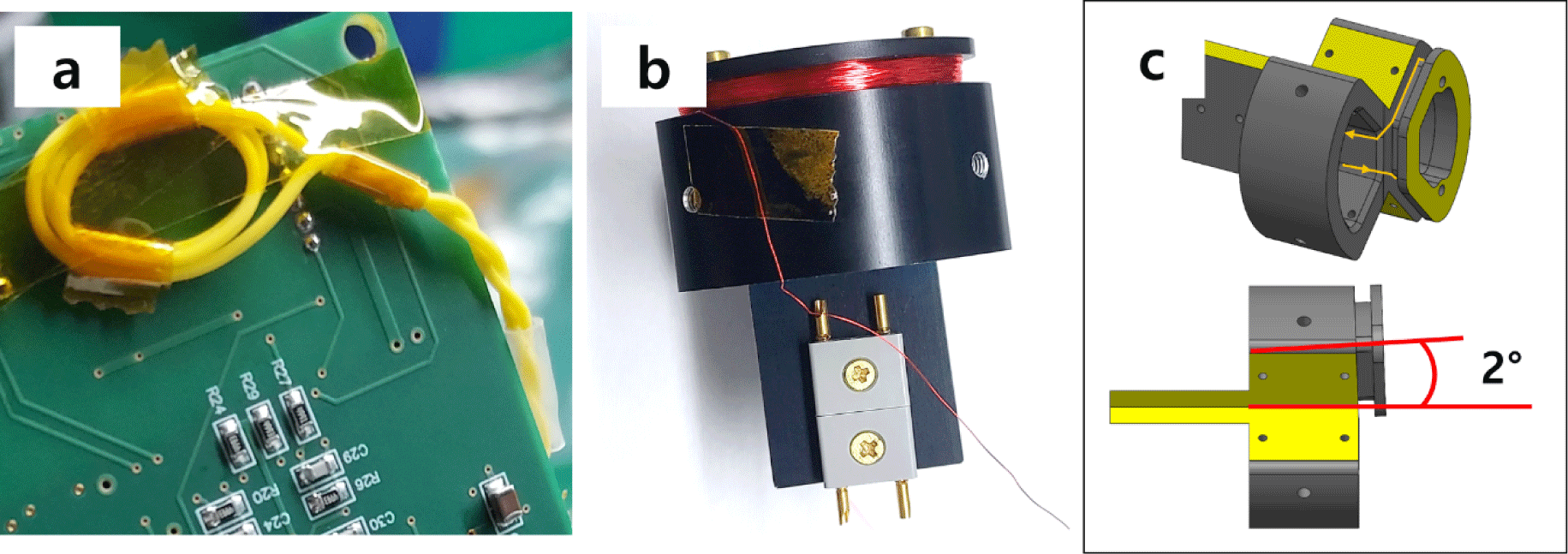
Through the KMAG mission experience, we learned that accurately determining the continuously changing offset of sensors is important for data calibration. As an enhanced solution, an offset calibration coil was added and connected to the MAMS module to determine the offset of each sensor by generating an artificial signal. The coils were installed at two locations: one was near the AMR sensors of the MAMS module (Fig. 6(a)), and the other was in the middle of the two FGMs in the boom (Fig. 6(b)). As they were tilted with respect to all three axes of the magnetometers, the magnetic pulse generated by the coils was detectable across all three axes (Fig. 6(c)).
The offset determination principle is illustrated in Fig. 7. It was assumed that the offset of the magnetometer varied. When the offset calibration coil generated symmetric bipolar pulses, the magnetometer detected a combined signal, including artificial pulses and varying offsets. Because the information about the pulses is already known, we can estimate the offset by averaging the pulses from the measured data.
We confirmed that the sensor resolution could change owing to temperature and radiation effects during the environmental tests. In such cases, coil pulses can be effective for data calibration. The pulse-generating circuit is a simple setup comprising a transistor switch, wire, and resistor, which minimizes the effects of external conditions. This allows the coils to produce pulses of consistent strength. Therefore, if the width of the pulse detected by the sensors changes during the mission, it indicates that the sensor resolution is changed by external factors. The variation in the pulse width can be calculated and used for data calibration.
The flight model (FM) of the MAMS module is shown in Fig. 8. The main microprocessor of the module is an MSP430i2040. There are connecting holes for the communication line, power line, and coil wire. The system specifications of the modules are listed in Table 2.

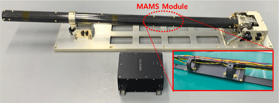
The MAMS module FM was secured in a 2 mm thick aluminum case and installed on the internal structure of the LSMAG boom. The LSMAG FM including the MAMS module is shown in Fig. 9.
3. SPACE ENVIRONMENT TESTS
The test was conducted in two categories: a performance and functional test, which determines whether the system is operating properly as intended, and an environmental test, which verifies the system functionality under an extreme environment.
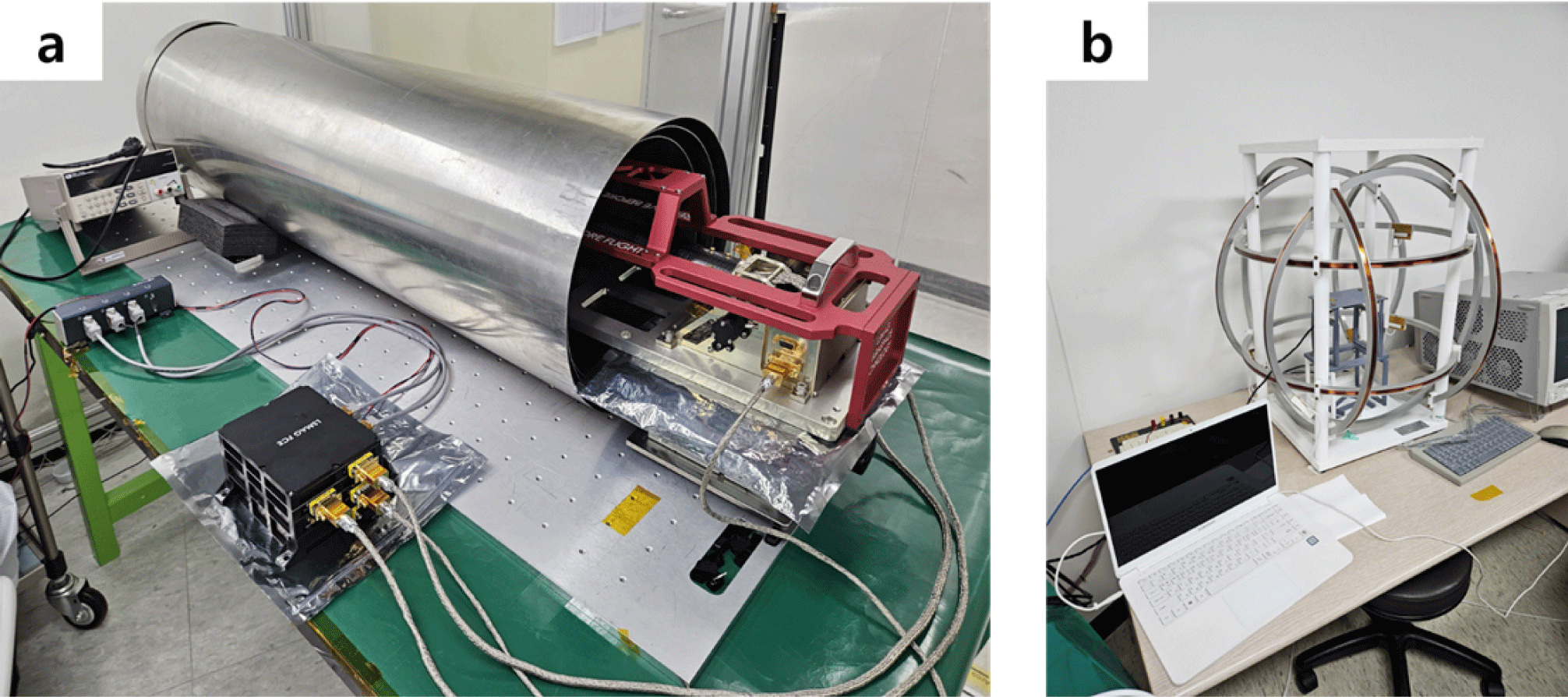
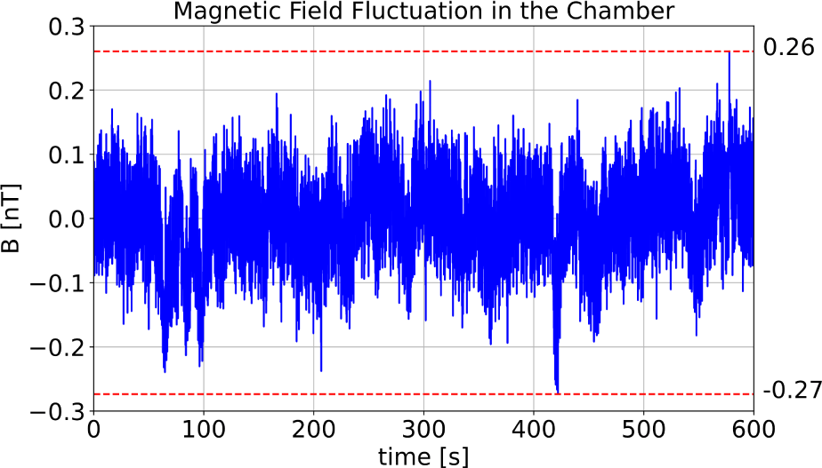
For the performance and functional test, a triple-layer mu-metal chamber was used to block external magnetic disturbances. A Helmholtz coil was employed to calibrate the sensor by applying an artificial magnetic field (Fig. 10). To verify whether the mu-metal chamber effectively blocks external magnetic fields, the LSMAG FGM measured the internal magnetic field, which remained stable within 1 nT for 10 min (Fig. 11). As FGM is sensitive to temperature variations, the data was acquired after an hour of thermal stabilization.
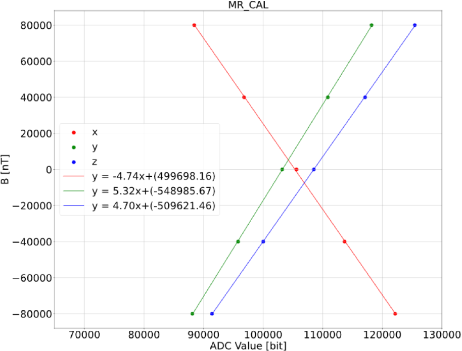
In the performance test, the resolution, measurement range, and noise levels of the AMR sensors and the accelerometer were evaluated. These requirements are summarized in Table 1 of Section 2.2. The Helmholtz coil was used to verify the measurement range and resolution per bit of the AMR sensor. We sequentially applied magnetic fields of −80,000, −40,000, 0, 40,000, and 80,000 nT along a single axis using the Helmholtz coil. No magnetic field was applied to the other axes during this process. The same procedure was repeated for the X-, Y-, and Z-axis. These results are shown in Fig. 12.
The noise and stability of the AMR sensors were tested using the mu-metal chamber. The MAMS module was placed at the center of the chamber to measure the zero-field conditions. Because the AMR sensor is sensitive to temperature variations, each measurement lasted for at least 1 hr to ensure the thermal equilibrium of the AMR sensors with room temperature. A random 30 sec segment of the data after thermal equilibrium was analyzed. By subtracting the mean value from this 30 sec data, the stability graph of the AMR sensors was plotted, as shown in Fig. 13. For the noise analysis, 5 min data were used, and the results are shown in Fig. 14.
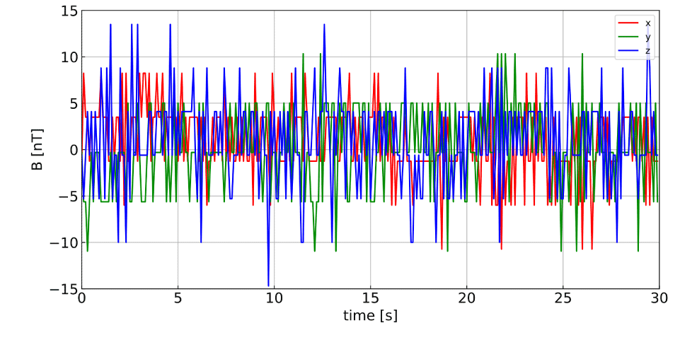

The test shows that at 1 Hz, the noise levels of the AMR sensors are 1.38, 1.67, and 1.19 nT/√Hz for the X-, Y-, and Z-axis, all meeting the required specifications. The stability tests revealed that the maximum difference between the adjacent samples did not exceed 20 nT, thus satisfying the stability requirements.
Unexpected noise was detected at approximately 4 Hz. By comparing the past data from various test environments, we found that the noise was generated at the test facility. Both FGMs detected the same noise at the same frequency. KMAG also detected and verified the noise that was generated by the test facility (Lee et al. 2021).
The measurement range and resolution per bit of the accelerometer were verified by tilting the MAMS module. The module was fixed in a vise and tilted to create both +1 and −1 g environments. A level was used to ensure alignment with the direction of gravity. This process was repeated for all three axes to confirm the accelerometer’s measurement range. The slope of this equation represents the resolution per bit obtained by a linear approximation of the measured values at each acceleration level. The results are shown in Fig. 15.
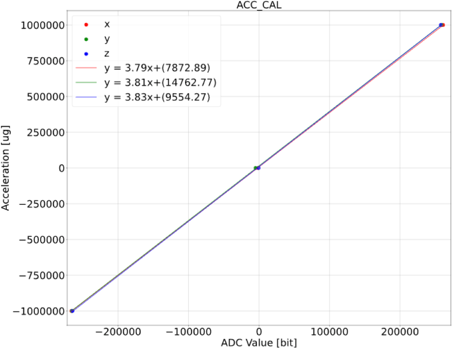
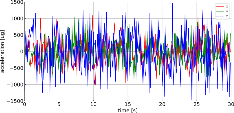
The noise and stability of the accelerometer were confirmed in the same manner as those of the AMR sensors. The stability test results (Fig. 16) show that the maximum difference between the adjacent samples did not exceed 6 mg. The noise test results (Fig. 17) show that at 1 Hz, the accelerometer noise was 41.7, 94.2, and 46.3 μg/√Hz on the X-, Y-, and Z-axis, satisfying the requirements listed in Table 1.
In the functional test, the power supplied to the MAMS module was checked, and its operation was verified through the MAMS module graphical user interface by executing the assigned commands. As expected, the sensors operated properly, communication was smooth, and the module responded to the commands.
The MAMS module receives power from LSMAG at 9 V. However, the module can operate within a voltage range of 5–16 V. To verify this, the test was conducted by supplying power in 1 V increments from 5 V to 16 V using an external power supply unit. The 5 V power was supplied through the separated 5 V power pin on the module circuit, while 6–16 V was supplied through the general power pin. The MAMS module operated normally across this voltage range, and the input current was constant at 32 mA regardless of the voltage. This was caused by LP2992, which lowered the input voltage from 6 to 16 V to 5 V. Because LP2992 is a linear voltage regulator, not a transformer, the input current remains constant as long as the output voltage and current are steady (Texas Instruments, 2023). Given that the LSMAG supplies 9 V of power to the MAMS module, the standard power consumption of the module is 288 mW.
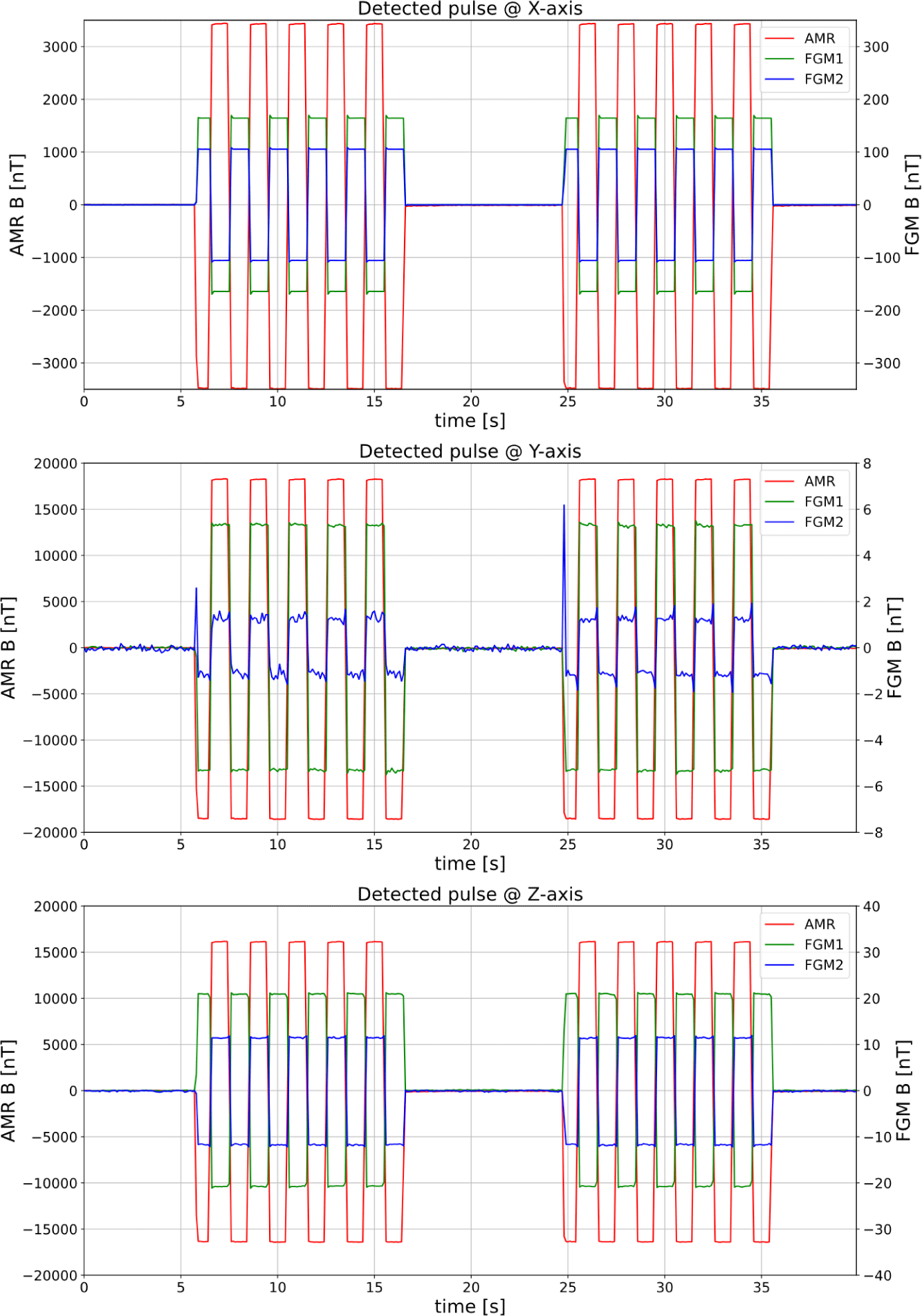
The offset calibration coil operated as designed, and the output was detected. Fig. 18 shows the detected pulse with the average value subtracted from the actual value. The minimum ratio of the detected pulse’s peak-to-peak value to the sensor resolution was 11:1 on the Y-axis of FGM2; therefore, the actual data and pulses will be clearly distinguishable during the mission. We found that the noise included in the detected pulses was particularly noticeable on the Y-axis of FGM2. This was mainly due to the intrinsic system noise of the FGM2 sensor, which is larger than that of FGM1. And the spike-like noise was caused by the timing issue between the MAMS module and FGM2. However, the offset determination using the calibration coil is still available because the pulses were symmetric. Since this method involves averaging the pulses, symmetry is more critical than precise pulse intensities and pulse deviations will be less significant.
A total of five types of environmental tests were conducted on the MAMS module (Table 3, Fig. 19). The test criteria and set-up followed the General Environmental Verification Standard (GEVS) requirements of the CLPS program. Additionally, the vibration test was based on Rideshare Payload User’s Guide (RPUG; SpaceX 2022). For some test items where the GEVS and RPUG standards were not specified, we applied KPLO or LSMAG requirements as supplementary criteria.
| Test | Model | Standard | State |
|---|---|---|---|
| TID | EQM | KPLO | Pass |
| TVAC | FM | LSMAG |
1st: fail 2nd: pass |
| EMC | EQM | GEVS, KPLO | Pass |
| Vibration | EQM | GEVS, RPUG, KPLO | Pass |
| Shock | EQM | GEVS, KPLO | Pass |
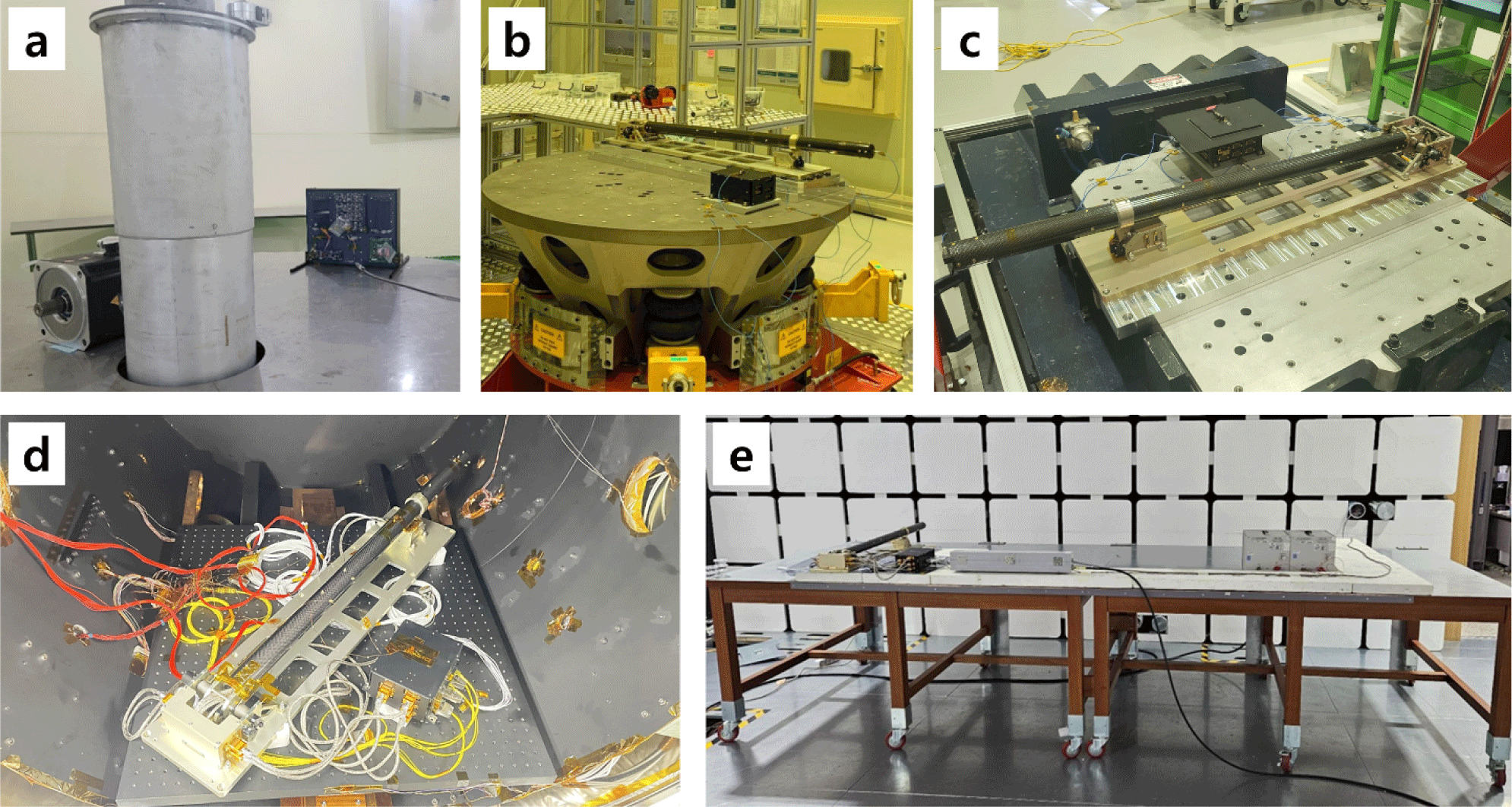
The first test is a total ionizing dose (TID) test. The KPLO TID test standard for the 2 mm thick aluminum case was used with an additional 30% margin, setting the test standard at 12.7 krad. The KPLO TID standard is based on the radiation exposure expected during KPLO’s ballistic lunar transfer trajectory. As the CLPS lander is expected to take a shorter trajectory to the Moon, the KPLO standard is considered stricter than the actual environment lander would face. The TID test was conducted at the Korea Atomic Energy Research Institute in Jeongeup on July 27, 2023, for 7 hr. As a result, the MAMS module was exposed to a cumulative 15 krad of gamma radiation, but maintained stable communication and normal operations throughout the test, successfully passing the test.
The second test was a vibration test conducted at the Korea Testing Laboratory (KTL) in Jinju, from September 21–22, 2023, covering the entire LSMAG system. The test included a resonance survey, sinusoidal vibration, and random vibration for all three axes. The resonance survey followed the RPUG and KPLO standards, and the sinusoidal vibration test followed the KPLO standard. For the random vibration test, the stricter between GEVS and KPLO criteria were applied at each frequency. The LSMAG system met all standards. Although some components detached during the test, the system was reassembled and retested. We confirmed that there was no change in the natural frequency characteristics after reassembly, suggesting that there was no impact on the test results.
The third test was a shock test conducted at KTL on the entire LSMAG system on November 15, 2022. Both the KPLO and GEVS criteria were applied to this test. A drop-shock test was conducted and the result converted into shock response spectrum. LSMAG met the test requirements.
The fourth test was a thermal vacuum chamber (TVAC) test conducted according to the temperature requirements of the LSMAG system. Both the MAMS module and the entire LSMAG system were included. The temperature range was from –37°C to 65°C and the air pressure kept under 1.0 × 10⁻⁵ torr. Two rounds of testing were conducted. The first was conducted on October 10, 2023, at the KASI. During the test, the LSMAG system was halted because of the short circuit caused by thermal contraction. An uninsulated pin projected out from the board. Because of the thermal contraction, this pin made contact with the adjacent wall of the module case at low temperature. Because the case was connected to the ground, a short circuit formed, halting the system. After trimming and insulating every potentially problematic pin, the second test was conducted at KTL from November 17 to 23, 2023. After two rounds of testing, the module successfully passed.
The fifth test was an electromagnetic compatibility test conducted at the International Certification Registrar in Gimpo from September 4 to 5, 2023. The test covered the entire LSMAG system and followed the GEVS standard, with some tests also applying the KPLO standard. The tests included conducted emissions in differential and common modes, radiated emissions in electric and magnetic fields, and electrical bonding. All the standards were satisfied.
4. RESULT
The MAMS module was developed to support the mission of the LSMAG, such as measuring an unexpected magnetic field and the attitude of LSMAG. The AMR sensors measure a magnetic field in the range of ± 80,000 nT with a resolution of 20 nT; the accelerometer has 6 mg resolution and ± 2 g measurement range on Earth. During the MAMS FM development phase, the space environment test was conducted, and its performance, functionality, and survivability were verified.
The MAMS module is able to perform four kinds of mission supporting roles:
-
Measuring a strong magnetic field
-
Detecting a noise signal
-
Generating a signal for offset calibration
-
Providing attitude information
The first role allows the LSMAG to maintain its mission when it encounters an unexpectedly strong magnetic field, which can limit measurements using FGMs. In this case, the LSMAG can maintain its mission using AMR sensors, as they can measure stronger magnetic fields than FGMs.
The second role is a major means of data noise calibration. The AMR sensors mounted inside the boom are located close to the lander. They can measure the magnetic field generated by the lander, and these data will be useful for processing lunar surface magnetic field data.
The third role contributes to the offset determination of the main fluxgate sensors. Previous offset determination methods relied on the fluctuations of the surrounding magnetic field. However, because the LSMAG is part of a stationary system with a short mission duration, we introduced an active method that generates a known signal for this purpose. An externally connected coil generates an artificial magnetic pulse, and by referring to this pulse, we can determine the offset of the magnetometers.
The fourth role is important in magnetic field measurements. The LSMAG can acquire its boom’s attitude information from the accelerometer on the MAMS module. In addition, the MAMS module can serve as a backup system for the lander using an accelerometer. In the case of the lander’s attitude measurement of system failure, the attitude data from the accelerometer can be used to estimate the lander’s attitude.
The MAMS module can function by itself even though it is part of the LSMAG system. As the module is equipped with its own MCU and follows the standard universal asynchronous receiver/transmitter protocol, it does not require other specified interfacing devices. The module can independently acquire data and communicate directly with the spacecraft as long as the proper power and communication configurations are provided. In addition, the module operates within a wide input power range of 5–16 V.
We are planning a new version of the MAMS module, which includes multiple solar cells to determine the direction of the module. The module can already measure the attitude, but direction is also required for the independent operation. Therefore, we designed a direction estimation method by comparing the output power or voltage of multiple solar cells. We tested the relationship between the output voltage of the solar cell and the angle of incoming sunlight. A prototype frame of the solar-cell module was fabricated and verified.
We expect the MAMS module to be utilized for various missions beyond the lunar lander mission.

