1. INTRODUCTION
Space plasma constitutes 99% of the universe and exists in space and various celestial bodies, such as stars, planets, and galaxies. Plasma interactions can be explained by the electromagnetic force q (E + V × B) acting on the particles (Parks 2005). The motion of the plasma can be understood by the magnetic field because the particles in the plasma travel along the lines of the magnetic field. The interaction between the planet’s magnetosphere and solar wind plasma generates electromagnetic waves. The observation of magnetic fields and electromagnetic waves helps understand plasma, planetary magnetosphere, and planetary environments (Hospodarsky 2016). It also provides information about the planet’s surface and atmosphere, and its internal structures, which cannot be obtained using imaging equipment (Acuña 2002). Therefore, magnetometer and energetic particle detector are important instruments for space exploration missions that study the planets and near its environment in solar system (Bennett et al. 2021).
Various types of magnetometers have been used to observe space plasma since the 1950s (Gurnett 1998), and there are two main types of magnetometers, depending on their purpose: scalar magnetometers and vector magnetometers (Lenz & Edelstein 2006). Scalar magnetometers used for calibration and specified missions only measure the magnitude of the field and not its direction. Generally, vector magnetometers that measure the three orthogonal components of a magnetic field are applied (Ripka 2001). A fluxgate magnetometer (FGM) among vector magnetometers measures from the DC to a few hertz and detects the strength of the magnetic field (Korepanov & Marusenkov 2012). Meanwhile, the search coil magnetometer (SCM), ranging from mHz to kHz, conducts high-frequency phenomena observations and measures time-varying magnetic fields (Tumanski 2007). To observe low- and high-frequency magnetic fields in a space environment, previous space missions, such as Time History of Events and Macroscale Interactions during Substorms (THEMIS), Magnetospheric Multiscale (MMS), Van Allen Probes, and ARASE simultaneously employed SCMs and FGMs (Auster et al. 2008; Roux et al. 2008; Kletzing et al. 2013; Fischer et al. 2016; Russell et al. 2016; Matsuoka et al. 2018; Miles et al. 2018; Ozaki et al. 2018; Jannet et al. 2021).
We previously developed space-based FGM and ground-based SCM. The Korea Pathfinder Lunar Orbiter (KPLO) was launched in August 2022 and includes high-performance FGMs. The KPLO magnetometer (KMAG) was designed to investigate the magnetic field around the Moon (Lee et al. 2021; Jo et al. 2023). Park et al. (2022) had been studied magnetic cleanliness, and Lee et al. (2023) researched noise reduction techniques because distinguishing between the magnetic field generated by the spacecraft and the ambient field is an important issue in space magnetic field observation. A ground SCM was developed to detect the magnetic field related to an ultra-low frequency (ULF) study (Shin et al. 2016). However, a new space-based search-coil magnetometer is required to observe magnetic waves in space.
The scientific objective of space search coil magnetometer (SSCM) development is magnetic field investigation in cis-lunar space and near-earth environments. Magnetic waves occur in near-Earth space, such as magnetosonic waves, plasmaspheric hiss waves, and whistler-mode waves, and are generated in the frequency range of several hertz to several tens of kilohertz with an intensity up to pT (Chen et al. 2010; Chen 2015; Li et al. 2015, 2019; Ma et al. 2019). Given that the amplitude of waves is typically 10–100 pT Hz–1/2, the noise equivalent magnetic induction (NEMI) is required to achieve a value better than 10 pT Hz–1/2 at 1 kHz.
We made and tested the various types of sensors. The frequency response and NEMI were performed to compare the specification of each core using the same sensing coil. This paper is organized as follows. Section 2 provides a short description of the sensor principles and the primary parameters for improving the sensitivity. In section 3, we explain the details of an experimental model of SSCM. Section 4 describes test procedures to confirm their performance, and the results are presented in Section 5. Finally, Section 6 presents our conclusions.
2. SEARCH COIL SENSOR
The basic principle of a search coil is Faraday’s law (Coillot & Leroy 2012). When a time-varying magnetic field passes through a loop-shaped wire, a voltage is induced according to the following formula:
Vi is the induced voltage and Φ = ∯AB ·dA is the magnetic flux inside the coil with cross section A.
Let N be the number of turns in the coil, μe the effective permeability of the core, S the core cross section, and B the uniform induced magnetic field. The output voltage at the coil is (Tumanski 2007):
When B is fixed, the output voltage is primarily determined by N, S, and μe. Increasing N and S to improve sensitivity is effective in an environment where the design restrictions of size and mass are not large. However, SSCM measures relatively weaker magnetic fields than the ground SCM. Simultaneously, it should conform to various restrictions in response to allowable mass, power, temperature, and radiation (Coillot et al. 2010). Therefore, a ferromagnetic core is typically used to enhance the magnetic flux inside the coil under environmental constraints. The core plays a crucial role in determining the sensitivity and noise of a sensor. As the effective permeability of the core increases, the output voltage increases, and the noise decreases (Coillot et al. 2007). The effective permeability depends on the relative permeability (μr) of the core material and the demagnetization that relates to the length, diameter (Chen et al. 1991; Beleggia et al. 2009). The relative permeability of the core is defined as the magnetic flux density within a material divided by the magnetic field density within free space (Hospodarsky 2016). Thus, it is important to analyze the characteristics of the core based on its material and shape to optimize the sensor.
The SCM has been continuously enhanced to lighten the sensors and improve their performance in space exploration missions. Regarding the THEMIS SCM, Roux et al. (2008) used a 170 mm length 7 mm diameter rod core. The sensors were optimized using the diameter-to-length ratio to increase the effective permeability of the core. The SCM sensor for MMS increased the magnetic implications by placing the magnetic concentrators at the end of the 100 mm length core (Le Contel et al. 2014). The ARASE SCM used a hexahedral core with a length of 200 mm and a permalloy. The core length for ARASE is half the length of that for the Van Allen Probes, while there are no practical NEMI differences for the observation of electromagnetic waves (Ozaki et al. 2018). The design of Detection of Electromagnetic Emissions Transmitted from Earthquake Regions (DEMETER) SCM was based on a 170 mm long core that was built by stacking annealed permalloy strips. Increased sensitivity has been realized by winding more turns on a central coil (Séran & Fergeau 2005). The rod core was replaced with a thin hollow core, resulting in space allocation for the amplifier and battery inside the core, and a reduction in sensor weight (Grosz et al. 2010). An inner-ringed multi-pitch rods (IRMPR) structure was used instead of the traditional single-rod core structure. It demonstrated a lightweight core and improved its performance using an IRMPR core structure (Sun et al. 2022). A SCM has been optimized using various types of magnetic cores to observe weak magnetic fields under restricted conditions; rod core, hexahedron core, stacked core, hollow core, IRMPR core, and concentrator (Table 1). We investigated whether the sensitivity of the sensor could be improved while reducing the weight and volume. We performed sensor performance tests on three types of cores: the rod core, which is commonly utilized; the sheet-stacked core with higher sensitivity compared to other forms; and the rolling-sheet core, which is lighter in weight compared to other core shapes.
3. EXPERIMENTAL MODEL OF SPACE SEARCH COIL MAGNETOMETER
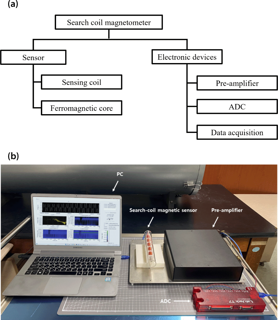
We used an experimental model of SSCM comprising a single-axis sensor and electronic devices (Fig. 1). The sensor consisted of a sensing coil and a ferromagnetic core. For the test of the experimental model, we used three kinds of cores: a rod core, a sheet-stacked core, and a rolling-sheet core. The electronics include a pre-amplifier for the signal amplification and a frequency-response flattening, and a data acquisition module (DAQ). The module consists of data acquisition program and an analog to digital converter (ADC).
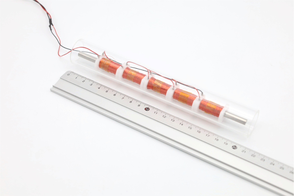
At the ends of the core, the magnetic flux density is reduced because of the edge effect phenomenon. In order to avoid the edge effect, the length of the coil has been shorter than the length of the core. The effective permeability of the core has a maximum value at the center of the rod and decreases further away from the center (Bozorth & Chapin 1942). Therefore, the optimal value of coil length has been determined by consideration of the edge effect and effective permeability. Considering the relationship between μe and the distance from the center of the rod core with dimensions of 200 mm (L) × 6.35 mm (D), it can be inferred that μe drops down to 3.8%, 15.2%, 34.2%, and 60.7% at 20 mm, 40 mm, 60 mm, and 80 mm from the center of the core, respectively (Hill 1962). This indicates that the coil could be positioned near the central part of the core to use μe efficiently. Consequently, we limited the core length to 75 mm from the center, where μe decreases by up to 30%. To reduce parasitic capacitance, we divided the sensing coil into five separate bobbins (Fig. 2). A copper wire with 36 AWG (36 SPN-155 RED, MWS Wire, Oxnard, CA, USA) was wound to 2,400 turns per bobbin, and the total number of turns was 12,000.
The inductance and parasitic capacitance of the sensing coil constrain the measurement range. To control the measurement bandwidth, we confirmed the inductance, and resistance (LCR) characteristics of the coil from 10 Hz to 40 kHz using an LCR meter (IM3533, HIOKI, Nagano, Japan) (Table 2).
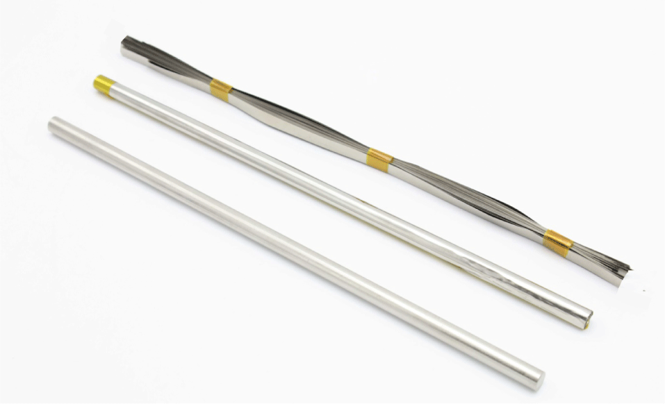
All three cores had a length of 200 mm (Table 3). The rod core is 200 mm long and 6.35 mm diameter, made of annealed nickel-based alloy. We constructed the sheet-stacked core with 0.0018 mm thick cobalt-based alloy sheet. The sheets were stacked to form cubes with dimensions 5 mm (W) × 4 mm (H) × 200 mm (L). We built the rolling-sheet core using 200 mm long, 0.051 mm thick annealed nickel-based alloy sheet, and it was rolled on top of the carbon fiber reinforced plastic (CFRP) tube to have 6 mm outer diameter of 1 mm wall thickness as shown in Fig. 3.
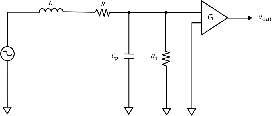
The coil exhibits resonance, where the induced voltage peaks at a specific frequency. If significant resonance occurs, the induced voltage of the coil may exceed the operating voltage of the system. This causes saturation, rendering it impossible to measure the entire frequency range. Therefore, we applied the Attenuation Resistor (AR) method to damp the frequency response near a resonance by connecting a parallel resistor R1 = 2.4 kΩ, which controls the Q factor (Quality factor) to prevent instability (Fig. 4). We added a 70 dB gain and low-pass filter. We also tested the flux feedback method. The feedback coil was wound with a 0.127 mm wire in the opposite direction to the sensing coil. The coil resistance is 3 Ω. It is placed at the end of core and sends the negative feedback signal to the sensing coil.
4. TEST METHODS
We confirmed the response of the sensor to an input signal at various frequencies. This allows the derivation of the transfer function, which confirms the sensitivity of the sensor. The transfer function T (jw) is the ratio of the output voltage Vout from the sensor to the induced magnetic flux B passing through the search coil.
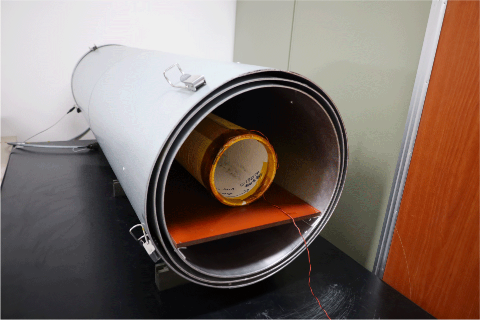
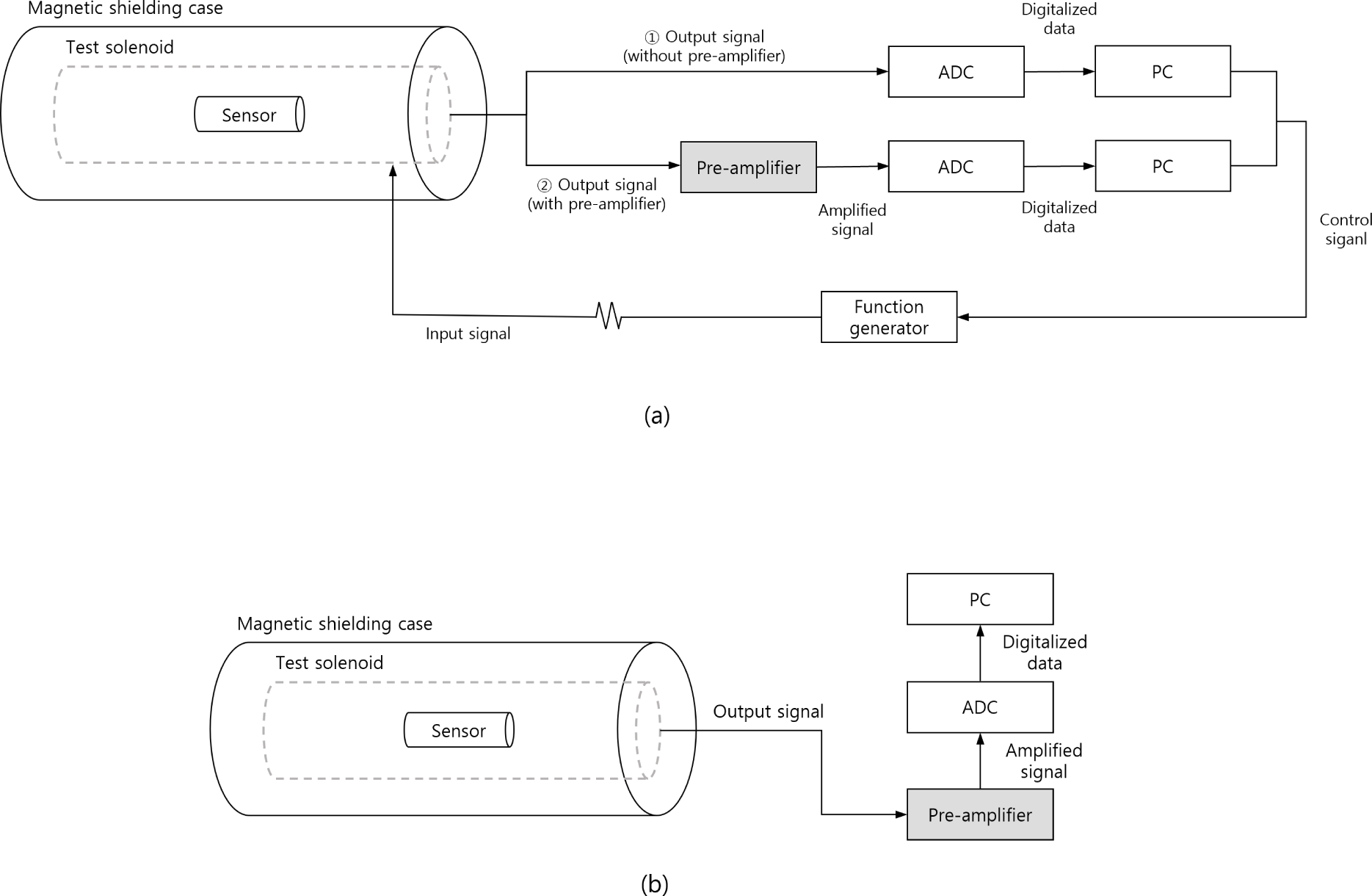
A test solenoid was employed to generate a time-varying magnetic flux across the sensor (Fig. 5). The test solenoid with dimensions of 1,250 mm (L) × 80 mm (D) and 360 turns produced a uniform magnetic field. We added an external resistor in series with the test solenoid to estimate the internal magnetic field when the function generator applied a signal [Fig. 6(a)]. A function generator (AG051, OWON, Zhangzhou, China) was connected to a PC to control the AC voltage. The sensor was installed inside a magnetic shielding case consisting of three layers of mu-metal to minimize electromagnetic interference. Our system employs a USB-based DAQ (LabJack T7, LabJack, Lakewood, CO, USA) with a 16-bit ADC to serve real-time monitoring. The DAQ is run by a program based on LabWindows/CVI (LabWindows/CVI, National Instruments, Austin, TX, USA). We also developed the measurement software using LabWindows/CVI for data monitoring, acquisition, and the fast Fourier transform (FFT) calculations. The sampling rate is 80,000 samples/s.
We tested NEMI, also known as threshold sensitivity and resolution. A smaller NEMI indicates a better performance of the sensor. NEMI is obtained by dividing the output voltage noise at the preamplifier input Eout by the transfer function T (jw) provided by Eq. (4).
The NEMI test was conducted by adding a pre-amplifier, unlike the frequency response. We measured the output voltage noise without applying an external magnetic field [Fig. 6(b)]. Subsequently, we confirmed the transfer function by applying an external magnetic field.
5. TEST RESULTS
We performed the frequency response tests of the three sensors up to a frequency of 40 kHz and compared it with the air coil. Fig. 7(a) shows the frequency responses of the four sensors excluding the preamplifier and compares it with the air coil. The air coil, rod-core sensor, the sheet-stacked core, and the rolling-sheet core sensor have resonance at 23.7, 2.6, 2.1, and 3.6 kHz, respectively. The responses at each resonance frequencies are much higher for core sensors than air coil. The core resonance affects the LCR characteristics of the sensing coil, leading to changes in their resonant frequencies and cover the wide bandwidths.
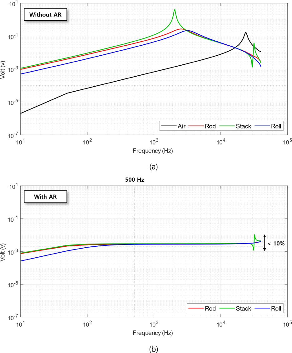
In Faraday’s law Eq. (2), the sensors were equivalent in all respects, except for effective permeability and core’s cross-section. The core cross-sections for the sheet-stacked core, rod core, and rolling-sheet core are 31.6, 20, 15.71 mm2, respectively. The rod-core sensor shows an induced voltage difference of 661 times greater than that of the air coil, the sheet-stacked core sensor displays a voltage difference of 749 times greater than that of the air coil, and the rolling-sheet core sensor is 235 times greater compared with the air coil at 10 Hz [Fig. 7(a), Table 4]. Therefore, when considering the differences in core cross-section of the sensors, the sheet-stacked core has the largest permeability among the three cores, followed by the rod core, and the rolling-sheet core. When using a stacked core with cobalt-based alloy, a secondary resonance occurred at 30 kHz.
| Frequency (Hz) | VRod / VAir ratio | VStack / VAir ratio | VRoll / VAir ratio |
|---|---|---|---|
| 10 | 661 | 749 | 235 |
| 100 | 159 | 186 | 59 |
| 1,000 | 154 | 237 | 63 |
| 10,000 | 7 | 7 | 7 |
| 40,000 | 2 | 1 | 2 |
The AR method is used to prevent sensors, including core, from exceeding the operating range due to resonance phenomena. However, for the low sensitivity air coil, the use of the AR method is unnecessary. The frequency response tests with the AR were conducted for three core types, but not for the air coil [Fig. 7(b)]. The voltages of all sensors are proportional to ω from 10 Hz to 50 Hz. In the whole frequency range, the voltage of the sheet-stacked core sensor shows a difference less than 1.1 times with the rod-core sensor, and a difference within 3 times with the rolling-sheet core sensor (Table 5). The voltage of the rod-core sensor is 1.6 times greater than the rolling-sheet core sensor from 10 Hz to 250 Hz. However, as the frequency increases, the discrepancy between two sensors decreases, showing that the discrepancy is within 10% after 250 Hz. The voltage disparity of the three sensors is less than 10% after 500 Hz; this demonstrates that the sensitivity of the sensors is similar in this frequency range. When using a stacked core, a secondary resonance was still present.
| Frequency (Hz) | VStack / VRod ratio | VStack / VRoll ratio | VRod / VRoll ratio |
|---|---|---|---|
| 10 | 1.08 | 3.05 | 2.84 |
| 100 | 1.10 | 1.56 | 1.42 |
| 1,000 | 1.08 | 1.08 | 1.00 |
| 10,000 | 1.07 | 1.07 | 1.00 |
| 40,000 | 0.24 | 0.23 | 0.99 |
The rod core and the rolling-sheet core have a similar geometry, but air gaps between sheets in the rolling-sheet core could reduce the effective permeability. When the length of the rolling-sheet core is fixed, increasing the thickness of the rolling-sheet core increases the permeability; there are limitations (Grosz et al. 2010). We also confirmed the improvement in the sensitivity of the sensor with this same method in our experimental model.
To remove the resonance, we tested the flux feedback method of placing the secondary coil at the end of the sensing coil and the AR method. Both methods had the same effect of suppressing the resonance. The flux feedback method can result in secondary resonance owing to the secondary coil and requires an additional harness. Hence, the frequency response was flattened using the AR method without any undesired extra peaks or additional harnesses. Moreover, the level of sensor flattening can be optimized based on requirements.
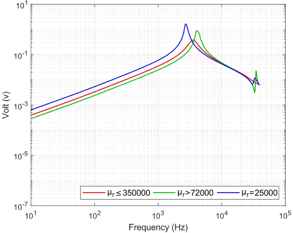
To determine the cause of high frequency fluctuations, we conducted the frequency response tests with identical core geometry but different core materials. Initially, we intended to use the sheet-stacked core type, but due to the material limitations, we chose the rolling-sheet core type. We used three distinct materials: sheets with μr ≤ 350,000, μr > 72,000, and μr = 25,000. Each sheet was rolled into three layers on top of the CFRP tubes with dimensions of 5 mm (D) × 200 mm (L).
Fig. 8 shows the frequency responses of the sensors depending on the core materials. The sensors made of cobalt-based alloys with a relative permeability lower than 105 showed the fluctuations at high frequencies. In contrast, the sensor made of the nickel-based alloy with relative permeability greater than 105 exhibited stable signals up to 40 kHz. Thus, regardless of the core geometry, core sensors composed of materials with low relative permeability exhibit fluctuations at high frequencies and are unsuitable for observing a wide frequency range.
We confirmed that sensors with rod-core and rolling-sheet cores could observe a magnetic field in the range of 10 Hz–40 kHz without high-frequency instability. We conducted the NEMI tests according to the requirements (10 Hz–20 kHz) using the rod- and rolling-sheet core sensors (Fig. 9). Table 6 indicates the NEMI values and the variance within the ±50 Hz range. The rod-core sensor exhibits the NEMI that is three times larger than the rolling-sheet core sensor in the frequency range of 10 to 50 Hz, where the sensitivity of the sensor is proportional to ω. The NEMI of both sensors differs by less than 1.3 times in the entire frequency range. The rod- and rolling-sheet core sensors had NEMI values of 0.014 pT Hz–1/2 and 0.012 pT Hz–1/2 at 1 kHz, respectively. The two sensors satisfy the NEMI requirement of 10 pT Hz–1/2 (@ 1 kHz). Peaks were observed at 10 Hz, 300 Hz, 900 Hz, and 1.5 kHz (Fig. 9). This is owing to noise, which can be explained by the test environment and power line noise.
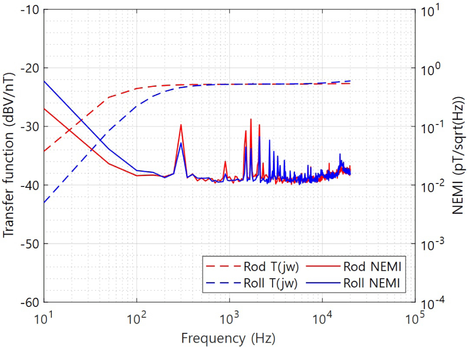
The mass of the rolling-sheet core was significantly lower than that of the rod core, whereas the resolution and sensitivity of the sensor were similar. In the band below 100 Hz, the relatively low sensitivity of the rolling-sheet core sensor can be compensated using a high preamplifier gain. Furthermore, we can improve the performance of the sensor by using a material with high relative permeability and thickening the wall of the rolling-sheet core. Therefore, the rolling-sheet core can replace the rod-core sensor to reduce the sensor weight and is suitable for measuring a wide frequency band.
6. CONCLUSION
We assessed the performance of the SSCM depending on the core type (rod core, sheet-stacked core, and rolling-sheet core) for a wide frequency band. The sheet-stacked core with a cobalt-based alloy (μr > 72,000) exhibited the highest sensitivity, although it exhibited fluctuations at high frequencies. The mass of the rolling-sheet core (μr ≤ 350,000) had a remarkable reduction compared with the rod core (μr ≤ 400,000), whereas there was no significant difference in sensitivity compared to the rod-core sensor. The NEMI of the rolling-sheet core sensor was 0.012 pT Hz–1/2 at 1 kHz, which satisfied the required NEMI standard. The rolling-sheet core sensor with high relative permeability is suitable for observing electromagnetic waves. In addition, it has the lightest mass and manufacturing flexibility. Thus, we will develop triaxial SSCMs with the rolling-sheet core with high relative permeability.

