1. INTRODUCTION
The Korean Pathfinder Lunar Orbiter (KPLO) was launched on August 4, 2022, by SpaceX’s Falcon 9. Before the lunar orbit insertion (LOI), KPLO completed the trans-lunar cruise (TLC) journey during 4.5 months on a ballistic lunar transfer (BLT) trajectory. In December 27, 2022, KPLO successfully settled down in a lunar polar orbit at an altitude of 100 ± 20 km after multiple LOI maneuvers (Song et al. 2023). Since January 1, 2023, KPLO has been operating in this polar orbit, passing over various regions of the Moon per its one-year mission plan.
The major scientific objective is to conduct a magnetic investigation near the Moon. Lunar surface magnetic anomalies are one of our scientific targets (Hood et al. 1979; Baek et al. 2017; Garrick-Bethell & Kelley 2019), with lunar magnetic induction another major scientific objective (Dyal & Parkin 1971; Russell et al. 1981; Hood et al. 1999; Haviland et al. 2019). The ARTEMIS P1/P2 (THEMIS B/C) spacecraft operation provides an excellent reference to study the lunar magnetic induction by KPLO magnetometer (KMAG) observation. The technical objective is a demonstration of multi-sensor operation of the KMAG instrument, which is composed of commercial-grade parts.
The expected KPLO lifetime was one year, but it has been extended over two more years because of sufficient fuel and stable health status. During the first and second years, KPLO operates at an altitude of 100 km, which is too high to investigate the lunar surface magnetic field because the magnetic field intensity is less than 3 nT at that altitude (Richmond & Hood 2008). However, the KMAG shows reasonable observation results when compared with surface vector mapping (SVM) data (Tsunakawa et al. 2010). During passage through the magnetic anomaly regions, KMAG data shows comparable magnitude and shape at the corresponding locations. Moreover, several times we have captured the lunar-induced field phenomenon from the lunar interior driven by rapid changes in the interplanetary magnetic field (IMF). Lunar magnetic induction has been suspected since the Apollo era (Dyal et al. 1976). Similar to the Apollo-era method, we use two ARTEMIS spacecraft in a highly elliptical lunar orbit as a reference for the IMF to identify lunar-induced responses in KPLO measurements close to the Moon.
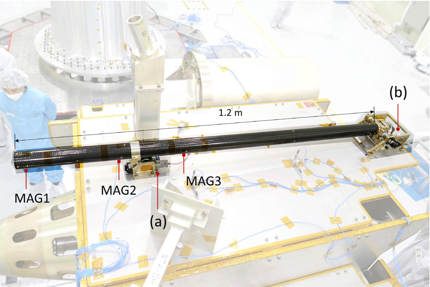
To minimize magnetic interference from the spacecraft, previous lunar missions like Lunar Prospector (LP) and Kaguya placed magnetometers at the end of a boom, with boom lengths of 3.6 m (Binder 1998) and 12 m (Kato et al. 2010), respectively. However, KMAG has a relatively short 1.2 m boom. Consequently, KMAG was equipped with three triaxial fluxgate sensors for multi-sensor measurement and redundancy purposes. Additionally, to monitor the spacecraft-generated magnetic field, magnetoresistive (MR) sensor was installed within the spacecraft body, providing a measurement range of ± 60,000 nT and a resolution of 100 nT.
Utilizing these four magnetometers, KMAG observes the magnetic field around the Moon and processes the raw data into the final data products. The scientific data obtained from the KPLO mission will be released to the public through the Korea Aerospace Research Institute (KARI)’s planetary data system (KPDS) (Kim et al. 2017). Since KPDS complies with the PDS4 standard, used as a standard for planetary exploration scientific data, KMAG scientific data will be open as the PDS4 standard. Accordingly, the scientific data generated is divided into three levels: Raw, Partially Processed (PP), and Calibrated (CAL), accompanied by metadata explaining them as a product.
KMAG’s initial operations started 4 hr after launch. Early operation allowed KMAG to acquire sufficient observation data to confirm data-processing pipelines for each data level during the BLT cruise. To verify the accuracy of KMAG’s data processing results, we compared its observational data with magnetic field measurements from the DSCOVR spacecraft operating in the upstream solar wind. The comparison was performed taking into account the time-delayed responses of magnetic field due to the different observation sites (Maggiolo et al. 2017). Afterward, the data-processing pipeline was applied to KMAG lunar orbit. We also verified the lunar orbit data by comparing it with data from the ARTEMIS P1 and P2 spacecraft, that are in elliptical orbits around the Moon.
In this paper, we present the instrument overview in Section 2 and the data processing in Sections 3 and 4. Sections 5 and 6 describe the results and future works.
2. THE KMAG INSTRUMENT
KMAG is the first magnetometer instrument developed in South Korea for space exploration beyond the Earth, and it was designed to carry out only the most basic functions. The instrument specifications and performance are described in a previous paper (Lee et al. 2021). In the design stage, the magnetic cleanliness requirement was insufficient to obtain clean observation, and the boom length was also relatively short because of the limitations of mass and volume (Park et al. 2022). Therefore, KMAG has three fluxgate sensors installed inside the boom to use a multi-sensing technique. Based on the observation data from the nominal lunar operation, these attempts are inadequate to obtain a clean signal. Nevertheless, data-reduction processes such as using a high-pass filter and calculating moving averages allow the generation of a reliable dataset.
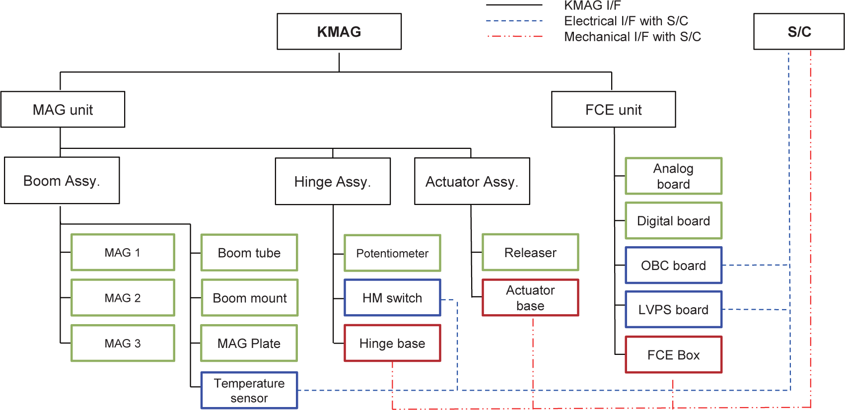
KMAG consists of two units: the MAG unit and fluxgate magnetometer control electronics (FCE) unit, as shown in Fig. 1. The MAG unit has three identical three-axis fluxgate sensors in the 1.2-meter carbon fiber-reinforced polymer (CFRP) boom that includes a hinge structure. The FCE unit has four boards: a low-voltage power supply (LVPS), an on-board computer (OBC), and digital and analog boards for fluxgate sensor operation. The OBC and LVPS boards have the same dimensions as a 1U CubeSat standard size (Fig. 2), and all electronic parts are commercial-grade except the connector and wire harness between the KMAG and the spacecraft. These major electronic parts are listed in Table 1.
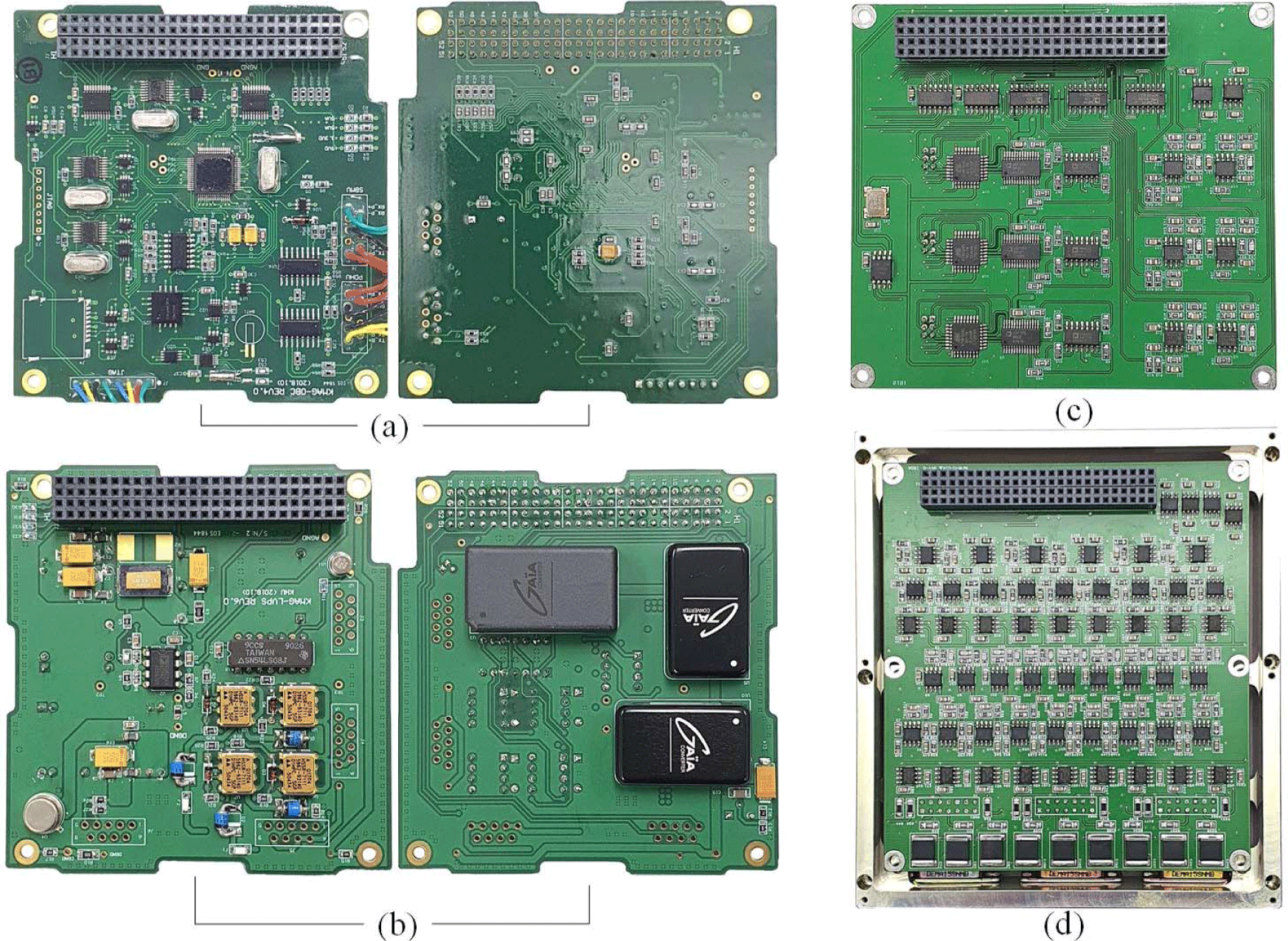
The OBC board has just a few lightweight functions that include RS422 communication, obtaining data at a rate of 10 Hz, and maintaining time sync with the spacecraft. The main processor used a commercial grade mixed-signal microcontroller. In the case of the flight firmware, we tried to reduce the command and data handling items to carry out essential functions only.
The OBC board has one anisotropic magnetoresistive (AMR) sensor (HMC1053) for the ground and in-orbit test purposes. Because of the temperature variation of the AMR sensor, there is a temperature senor on the board. It has proven to be a good reference (beyond expectations) to monitor large magnetic disturbances from the spacecraft for the in-orbit calibration.
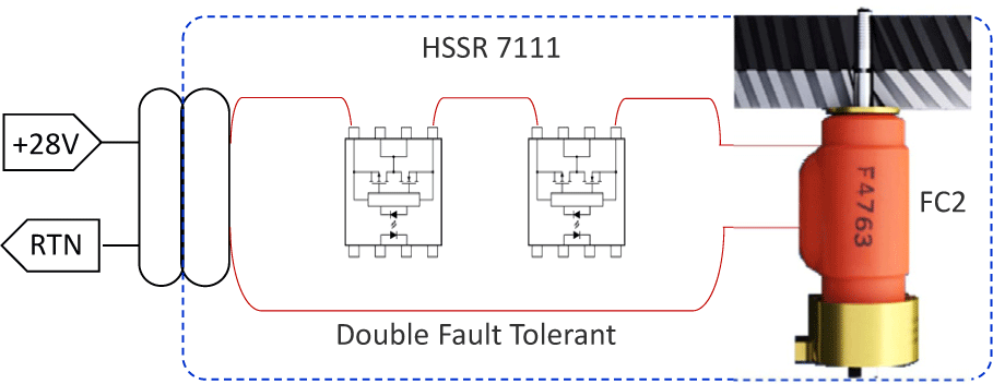
The LVPS board has two main components: the regulated voltage supply and the boom actuator control. The boom actuator circuit consists of two MOSFET Optocouplers (HSSR 7111) to supply high current to a Frangibolt (FC2) actuator as shown in Fig. 3. This circuit has redundancy.
The analog and digital boards incorporate three identical fluxgate sensors operating circuits for the three magnetometers, respectively. This means that one damaged circuit does not affect the others. The data acquisition continues during power-on, and the observation data is transferred by the OBC 10 Hz trigger signal. All circuit voltages (± 5 analog, + 5 digital) are provided by the LVPS through an internal PC-104 stacked connector.
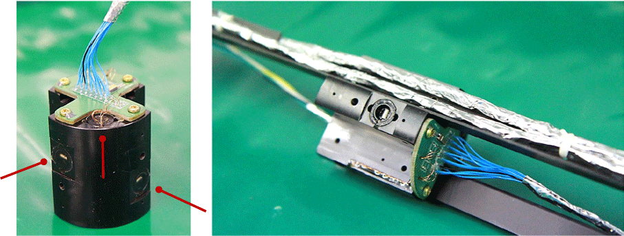
The fluxgate magnetometer was developed by Sensorpia Inc. The shape of the sensor core is a tiny racetrack (Son 2012). Each KMAG fluxgate magnetometer has three sensors that are installed in the magnetometer housing for three-axis observations as shown in Fig. 4.
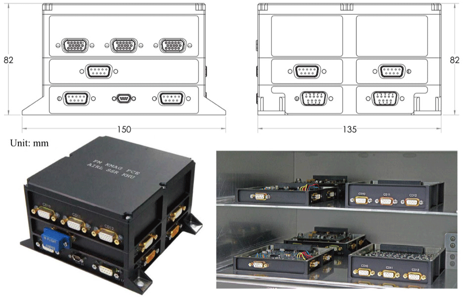
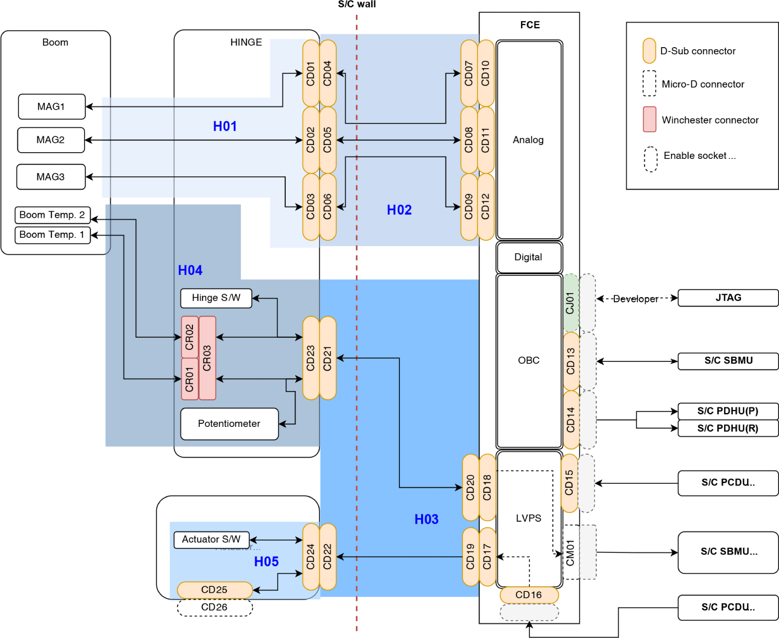
The mass of the KMAG instrument is 3.5 kg including wire and harness. Most of the mechanical structures use AL6061 alloy. The FCE box has a stack hold structure, as shown in Fig. 5. The electronics boards are assembled in each structure and then these structures are connected by screws. The FCE box has eleven connectors for all of the KMAG instrument function flows including communication with the spacecraft. The wire harness diagram is shown in Fig. 6.
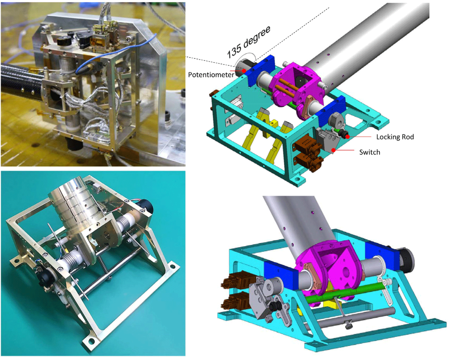
The hinge structure includes the boom rotation mechanism, electric connectors, and position sensors. For the rotation angle information, we used one micro switch (11HM1, Honeywell, Charlotte, NC, USA) and one potentiometer (6538, Bourns, Riverside, CA, USA). The deployment locking mechanism involves a locking rod inserted into the rotation axis structure when the boom rotation ends, as shown in Fig. 7.
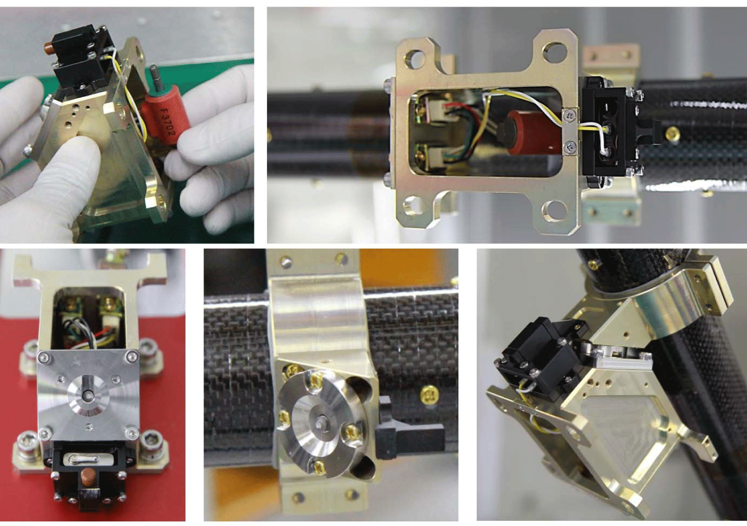
As shown in Fig. 8, the actuator assembly uses a TiNi FC2 Frangibolt and one micro switch. The micro switch assembly has a push spring pin to initiate the deployment force. This deployment mechanism was tested twelve times during the development stage. There were two failures, one caused by a defective epoxy bond and the other, by a mechanical design problem. The contact surface of separate plates has a slope for easy release. There are two connectors in this unit: a main power supply that comes from the LVPS, and an enable-plug to cut off the input power during unstable power supply conditions. The enable-plug connector was installed at the final stage just before the launch.
The KMAG did not use an instrument base plate (i.e., an interface structure) between the KMAG and the spacecraft because of the mass limitation as shown in Fig. 9. Therefore, we repeatedly carried out a variety of tests such as thermal and vibration to verify the safety of the direct attachment on the spacecraft top panel.
3. DATA PRODUCT
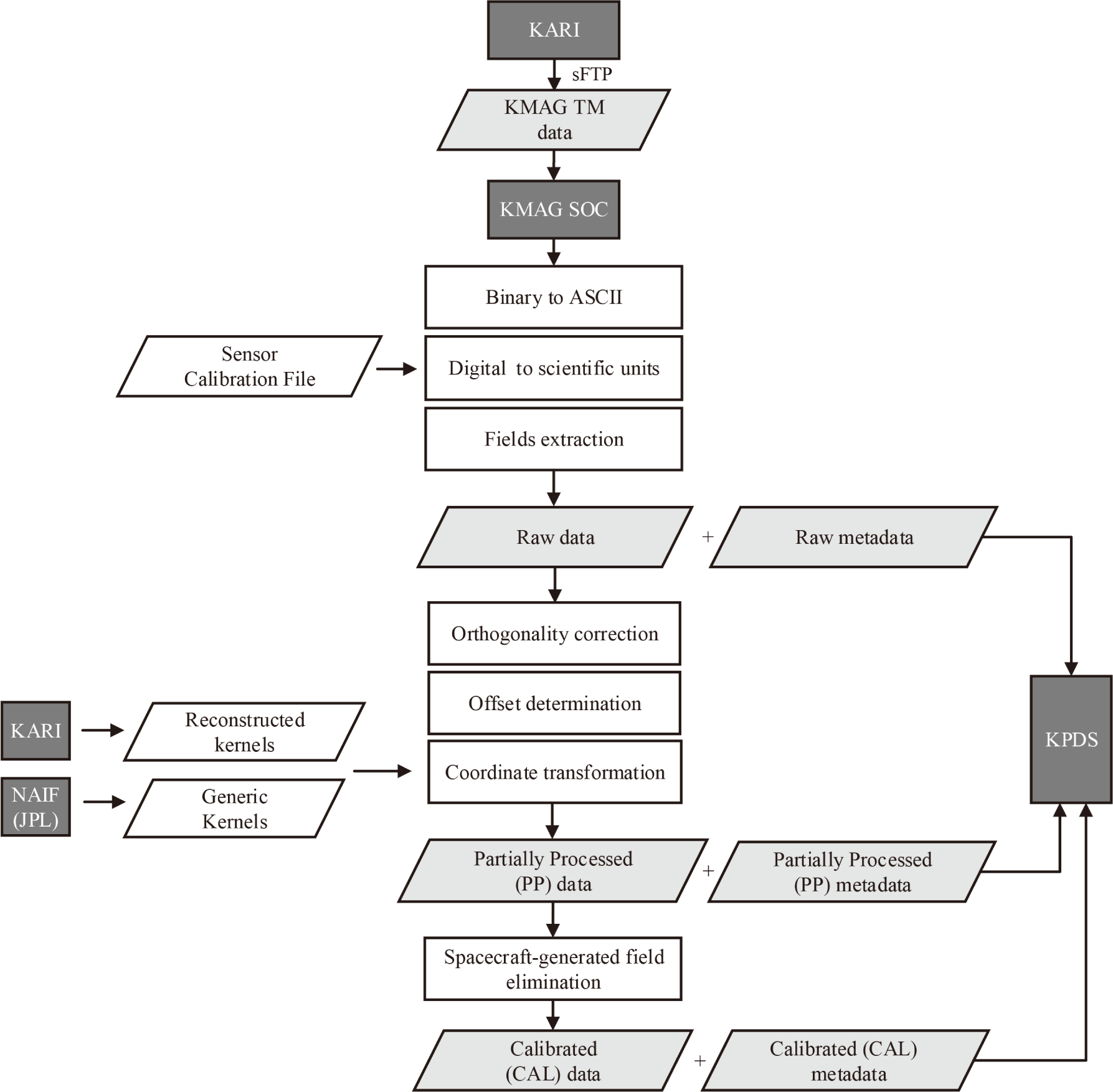
The KMAG data for over a year, since August 5, 2022, is available from both the TLC phase and nominal mission phase, except for about 20 days. This data has been archived by the KPLO deep space ground system (KDGS) in KARI, which supports the KPLO system rehearsals and mission operations (Song et al. 2021). The science data management subsystem (SDMS), one of the subsystems of KDGS, transmits science telemetry (TM) data. This data is sent to instrument science operation centers (SOCs) by the KPDS sFTP server, with the removal of channel access data units (CADU) header, tail, and padding. In addition, KPDS will release SOCs’ processed scientific data to the public with the PDS4 standard, established by NASA’s planetary data system, widely recognized as the standard for scientific data in the field of planetary exploration.
Hence, KMAG SOC processes the TM data into higher-levels of scientific data in compliance with the PDS4 standard. Ultimately, KMAG SOC generates data processed at the Raw, PP, and CAL levels according to the data levels defined in Table 2.
First, Raw data is extracted from TM binary data. This data contains magnetic field dataset and monitoring dataset. Secondly, the PP data undergoes instrument calibrations such as orthogonality correction and the sensor offset determination. Last, we perform a coordinate transformation correcting for spacecraft orientation using the SPICE toolkit and kernels. At this point, the PP data becomes a useful magnetic field dataset. Finally, the CAL level data (the end-user data) is achieved by calibration of spacecraft noise fields. This data is available for scientific research.
To create a single data product, we generate not only the primary scientific data, but also accompanying supplementary metadata for each level. Hence, we produce metadata in XML syntax; this includes details about the product, mission, and observations, as well as descriptions of the scientific data.
The format of the data product and the data transmission process were verified by creating an interface control document (ICD) and interface test procedure (TP) with KARI before the release of KPDS. Consequently, the processed scientific data and metadata are combined into a single product for multiple dates. The entire data-processing pipeline is shown in Fig. 10. Finally, the data-processing pipeline provides processed magnetic field data products at Raw, PP, and CAL levels.
4. DATA CALIBRATION
The final goal is to process the scientific data into CAL data, which is research-grade. Data calibration involves two main procedures: ground calibration, which is performed before launch, and in-flight calibration, which is carried out during the cruise phase. On the ground, we conducted calibration tests related to the characteristics of the instrument itself. From the ground calibration test utilizing Helmholtz coils, we derived equations that correct sensor offset and non-orthogonality. Additionally, we implemented a thermal test to evaluate the temperature dependency of the sensor. The temperature offset was found to vary by approximately 0.1 nT/10°C. However, the temperature calibration differs slightly depending on the slope of the temperature variation. In the lunar orbit, the temperature of the magnetometer sensor fluctuates by up to 10°C per orbit, resulting in a minor effect on the magnetic field change. Therefore, thermal correction was not applied to the initial public data.
Corrections of some parameters that are difficult to predict during ground testing are performed by in-orbit calibration. The elements of in-orbit calibration performed during the cruise are sensor offset variations, spacecraft orientation changes, and spacecraft noise fields. Since the study on removing spacecraft-generated magnetic fields is in progress, it will be covered in a later paper on noise removal.
In the initial measurements of KMAG, the maximum offset among the three magnetometers reached ~70 nT, which is believed to be caused by the magnetization effects from long-term storage prior to launch and the different operational environment. The zero offset determination is one of the most important stages in the entire data processing because the offset can change over a long period and an inaccurate offset can lead to a totally different result. To find the offset, previous missions employed various methods. For example, there are the spin-averaging technique (Farrell et al. 1995; Kepko et al. 1996) and the minimum variance analysis in the Alfvénic characteristics of solar wind, called the Davis-Smith (D-S) method (Davis & Smith 1968; Belcher 1973).
The KPLO is a three-axis stabilized spacecraft without spin. Thus, the KMAG adopts the D-S method, used in previous missions such as Mariner 5 (Belcher & Davis 1971) and Kaguya (Takahashi et al. 2009), which is applicable to KMAG employing three sets of three-axis fluxgate sensors. In the case of KMAG, the D-S method is applied individually to each fluxgate sensor to derive offsets along the three axes. This method can also be utilized as a correlation technique, as suggested by Leinweber et al. (2008).
The D-S method is based on two main assumptions: (1) During the observation period, the IMF intensity is stable compared to the other three vector components, indicating Alfvénic perturbations (Ness et al. 1964) and (2) the offset remains constant throughout that period. Hence, this method is suitable for solar wind with Alfvénic characteristics, where magnetic field variations primarily manifest in their direction rather than in their magnitude. Accordingly, the D-S method proposes to determine the zero-offset as the value that minimizes the variance of the squares of the total magnetic field.
The D-S method can be applied over intervals where the offset may be assumed to be constant. The time interval should be long enough to include averaged background magnetic field variations, while short enough to configure the entire period with a sufficient number of intervals. Therefore, we determine constant zero-offset within the intervals characterized by the Alfvén wave properties over the entire period.
The KMAG magnetic field measurement, M, can be expressed as the sum of the actual background magnetic field, B, spacecraft magnetic field, N, and sensor offset, O. To determine the sensor offset, the spacecraft-generated field has to be considered; but this will be done during higher-level data processing. Instead, we can select the dataset for which the spacecraft magnetic field (N) strength is much smaller than other two field (M and O) strengths. This condition can be confirmed by the same observation of all three magnetometers.
In this case, the measured magnetic field M is represented as the sum of the actual background magnetic field B and the sensor offset O:
The D-S method calculates a constant offset O that minimizes the variance of B2. Since B = M − O, the variance of within a single interval is defined by
where the parameter within angle brackets represents average value and the parameter with subscript i represents the time series values over the ith interval. Thus, the condition for minimizing the variance of B2 can be formulated as an equation in terms of Oi:
where Ci denotes the covariance matrix given by
Eq. (3) provides an expression for obtaining a constant offset considering variance only for a single short interval. To account for variance across the entire block comprising multiple intervals, we have
To determine offsets that change by a maximum of 10 nT/month, we apply Eq. (5) over every 8 hr block. Additionally, each interval comprising the block is set at a 10 min duration. Consequently, we apply the D-S method to each of the three fluxgate sensors, deriving three offsets per sensor. After the offset subtraction, we obtain zero-level measurements.
The subsequent coordinate transformation involves converting magnetic field measurements from KMAG’s sensor coordinate system to a spacecraft coordinate system, and then to Earth-centered and Moon-centered coordinate systems such as geocentric solar ecliptic (GSE), geocentric solar magnetospheric (GSM), selenocentric solar ecliptic (SSE), and selenographic (SEL) coordinates.
The KMAG sensor coordinate systems and the spacecraft coordinate systems are presented in Fig. 11. The origin of the spacecraft bus reference coordinate system is located at the center point of the propulsion rails and the top of the spacecraft adapter. The +X axis extends from the origin in the direction opposite to the propulsion module installed on the spacecraft. The +Z axis, also originating from the origin, runs parallel to the optical cameras and payload devices. The +Y axis completes the right-handed Cartesian coordinate system with the +X and +Z axes. KMAG’s sensor coordinate system is oriented with a 90° rotation (with respect to the spacecraft frame) about the Z-axis, followed by a negative rotation corresponding to the boom deployment angles about the X-axis. The transformation equation from magnetic field measurements in sensor coordinates BMAG to spacecraft coordinates BS/C has been designed and validated by ground testing. This equation includes the boom deployment angle φ.
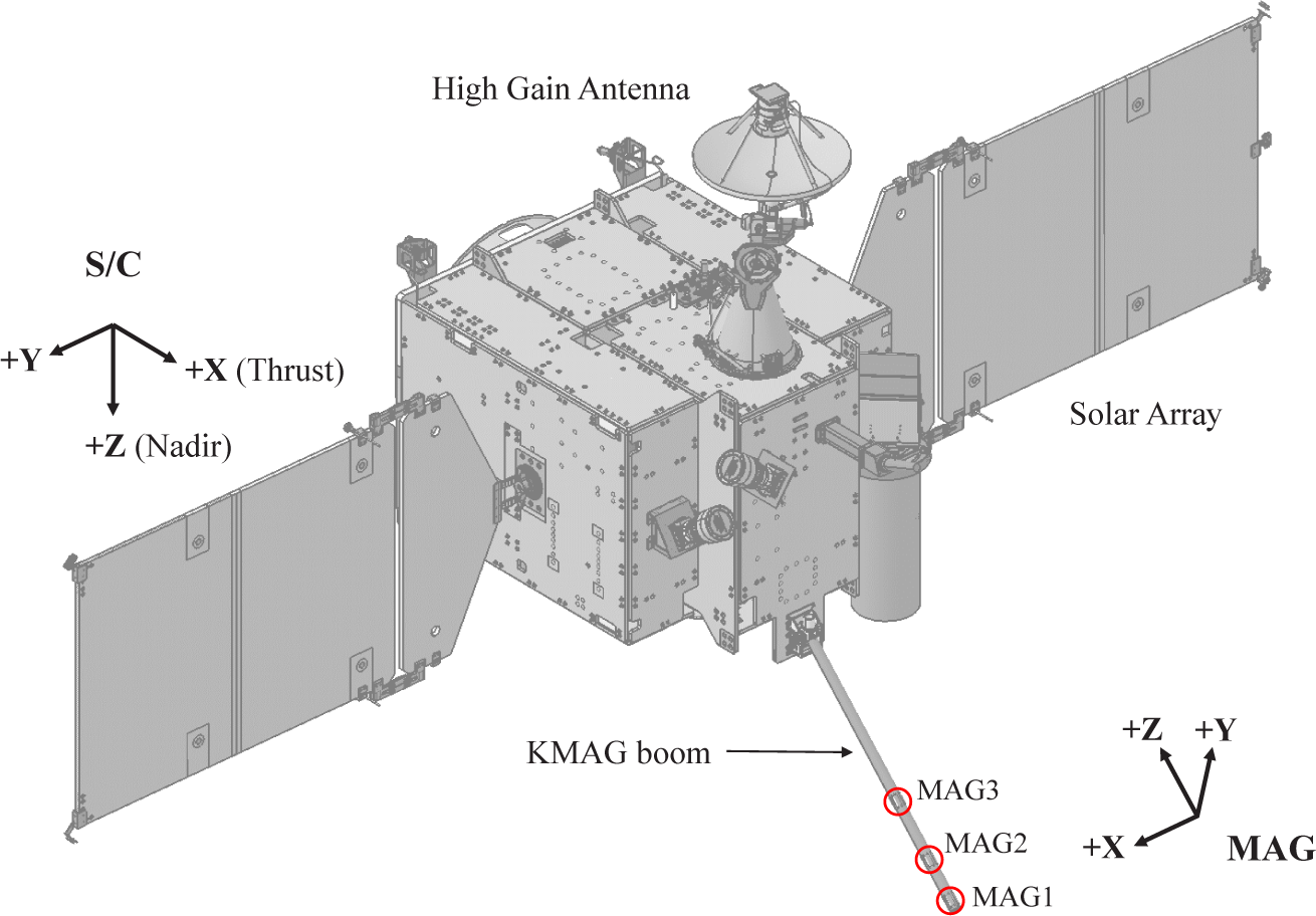
The boom deployment angle of the KMAG is set at 135°. During the operation, we receive the boom deployment angle as 1 Hz data to check for errors in the boom deployment angle. To obtain the equation of conversion to the spacecraft coordinates, we substitute this angle into Eq. (6).
Subsequently, using SPICE kernels such as the camera-matrix kernel (ck), which contains spacecraft attitude information, and the frame kernel (fk), which contains frame information, we obtain Euler angles to transform the spacecraft coordinates into various meaningful coordinate systems. To finally convert the spacecraft frame to the desired frame, we need fks for the target frame. We either use an existing fk or define a new fk. The newly defined fk is verified with Kaguya data in various coordinates. In conclusion, we obtain the magnetic field measurements in the desired frame by substituting Euler angles into the coordinate transformation equation. For instance, the ZYX Euler angles α, β, and γ that are used in the coordinate transformation equations to convert magnetic field observations from spacecraft coordinates BS/C to GSE coordinates BGSE are applied as follows.
As a result, we generate observation data in GSE, GSM, SSE and SEL coordinate systems. We also confirmed the reliabilities of the coordinate transformation equation by applying it to Kaguya data.
5. RESULTS
The data accumulated during 4.5 months in the TLC phase were suitable to carry out calibration tests because there were relatively few spacecraft maneuvers. In the case of general KMAG data processing, we first convert the binary TM file delivered through KPDS sFTP into ASCII and scientific units to confirm the data status and check errors. The monitoring data are stable and there are a few missing data points (1.52% for about a year). Then, the ground calibration factors like an initial sensor offset correction and orthogonality corrections determined on the ground are applied.
Afterward, the removal of the spacecraft fields becomes the priority. The noise field is removed by high-pass filtering, but a more precise removal method is currently under investigation. The next step is to determine the zero offset for each sensor.
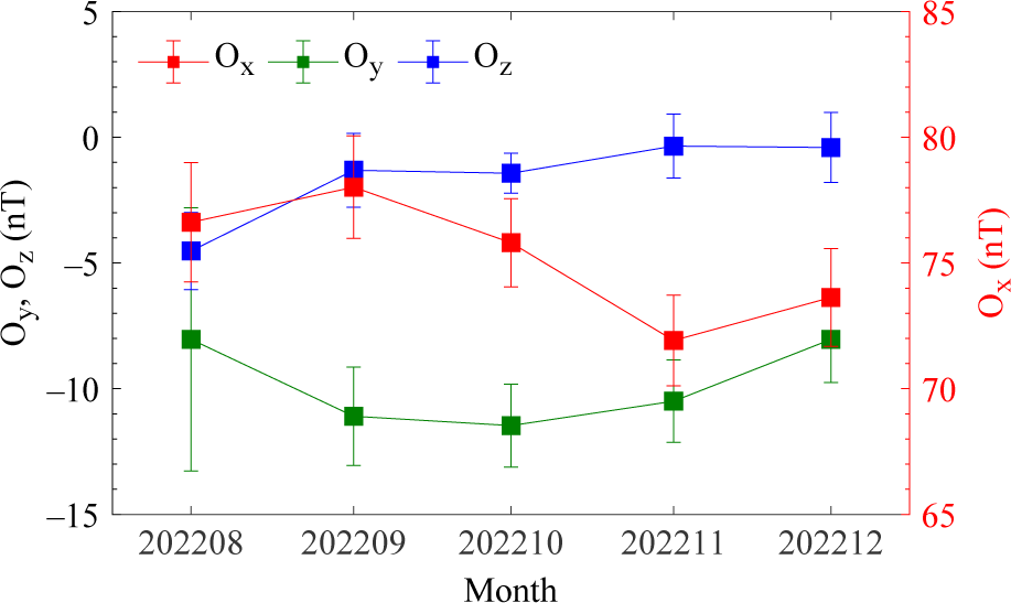
As previously mentioned, we apply the D-S method to 8 hr blocks consisting of 10 min intervals, resulting in three offsets per day for each sensor axis. The daily averaged offsets over the cruise phase are summarized in Table 3. The offsets for the representative dates with consistent spacecraft orientation remain stable within a range of 0.1–0.7 nT. The offsets exhibit an average variation of ± 2 nT for a month, with a maximum variation of ± 5 nT noted in August (shortly after the launch of KPLO). The ± 5 nT variations can be attributed to the initial phase of stabilization operations. Referring to Table 3 and Fig. 12, the offsets have changed by a maximum of approximately 5 nT over 4.5 months. Comparing this to the offset changes of Kaguya at 2 nT/5 month and THEMIS at 0.2 nT/6 month (Auster et al. 2008), the KMAG offsets display relatively larger variations. This suggests a substantial amount of spacecraft magnetic interference on the KMAG sensors, and the main reason is presumed to be the short boom length. Following the offset calibration, a coordinate transformation is performed using SPICE kernels and toolkits.
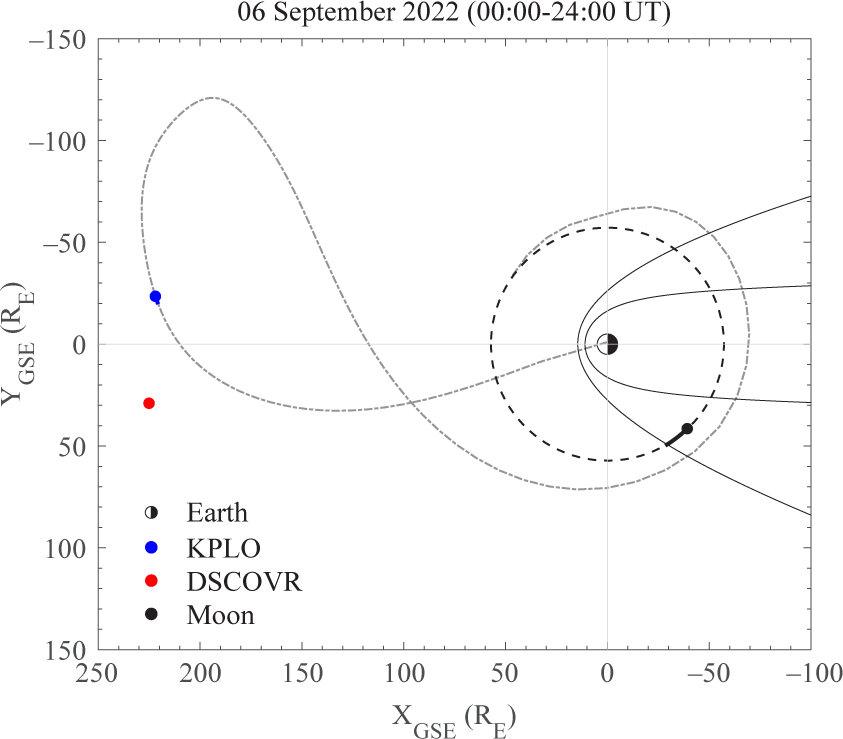
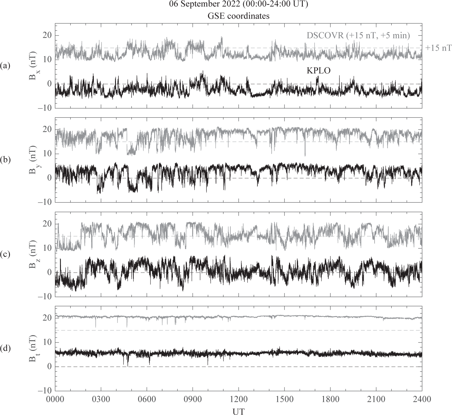
We compare IMF observations from the KMAG instrument onboard KPLO with the magnetic field data from DSCOVR, monitoring the solar wind, when KPLO was in the solar wind. This comparison is conducted under an assumption of a constant time delay between both satellites. Fig. 13 shows the KPLO (blue) and DSCOVR (red) trajectories in the GSE equatorial plane for the interval of 00:00-24:00 UT on September 6, 2022. During this 24 hr interval, DSCOVR moved from GSE (x, y, z) = (225.0, –23.5, 6.4) to (225.1, 29.1, 1.0) RE, and KPLO moved from GSE (x, y, z) = (220.6, –19.7, 5.7) to (222.0, –23.5, 6.4) RE. The KPLO’s overall BLT trajectory is indicated by the dashed-dotted line and the orbit of the Moon located at a radial distance of 57.2 RE is presented by the dashed circle. The solid curves represent the model bow shock by Fairfield (1971) and model magnetopause by Shue et al. (1998), respectively. Fig. 14 displays IMF variations over that period measured by KPLO (black) and DSCOVR (gray). The IMF vector quantities are in GSE coordinates. In timeseries plots, the DSCOVR magnetic field data are added to 15 nT and shifted to the right by 5 min for a comparison with KPLO data. The constant time delay of 5 min corresponds to a convection time of the solar wind between DSCOVR and KPLO. The 15 nT offset is marked by a horizontal dashed line in each component and total field intensity. The IMF variations observed at KPLO and DSCOVR exhibit very similar signatures with a mean difference less than 0.2 nT and a standard deviation difference less than 0.1 nT. After applying the D-S method to remove KMAG offset values, it has been confirmed that the KMAG instrument onboard KPLO accurately measures the solar wind magnetic field.
Fortunately, the KPLO is operating accompanied by the ARTEMIS P1 and P2 spacecraft, which have elliptical trajectories around the Moon and observe the magnetic field. The configuration of these three spacecraft provides a new insight into the lunar magnetic field investigation; moreover, P1 and P2 are the best references for the KMAG observation.
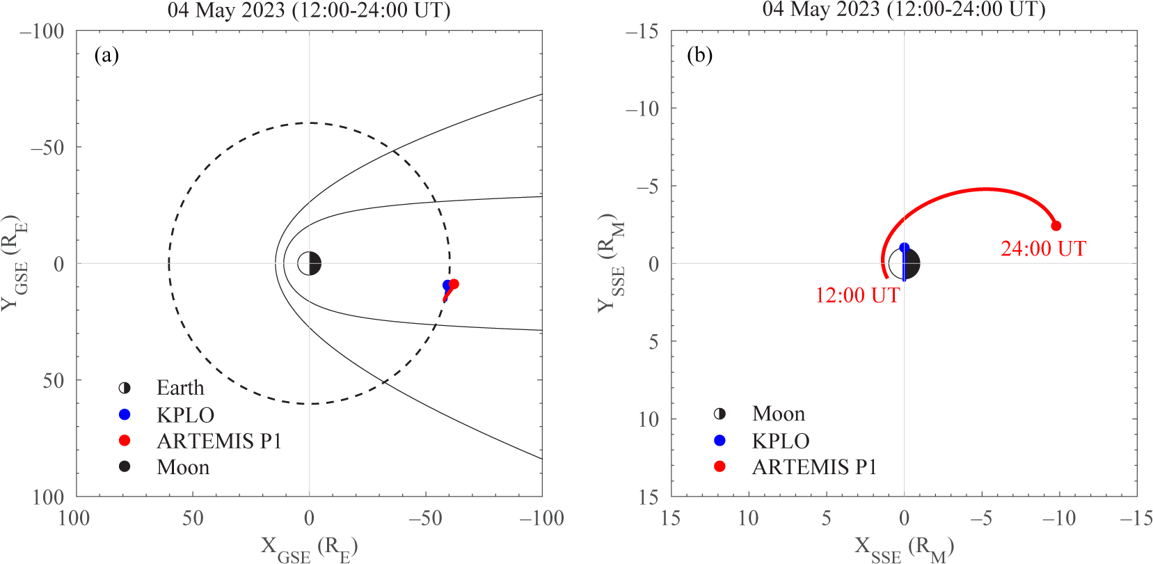
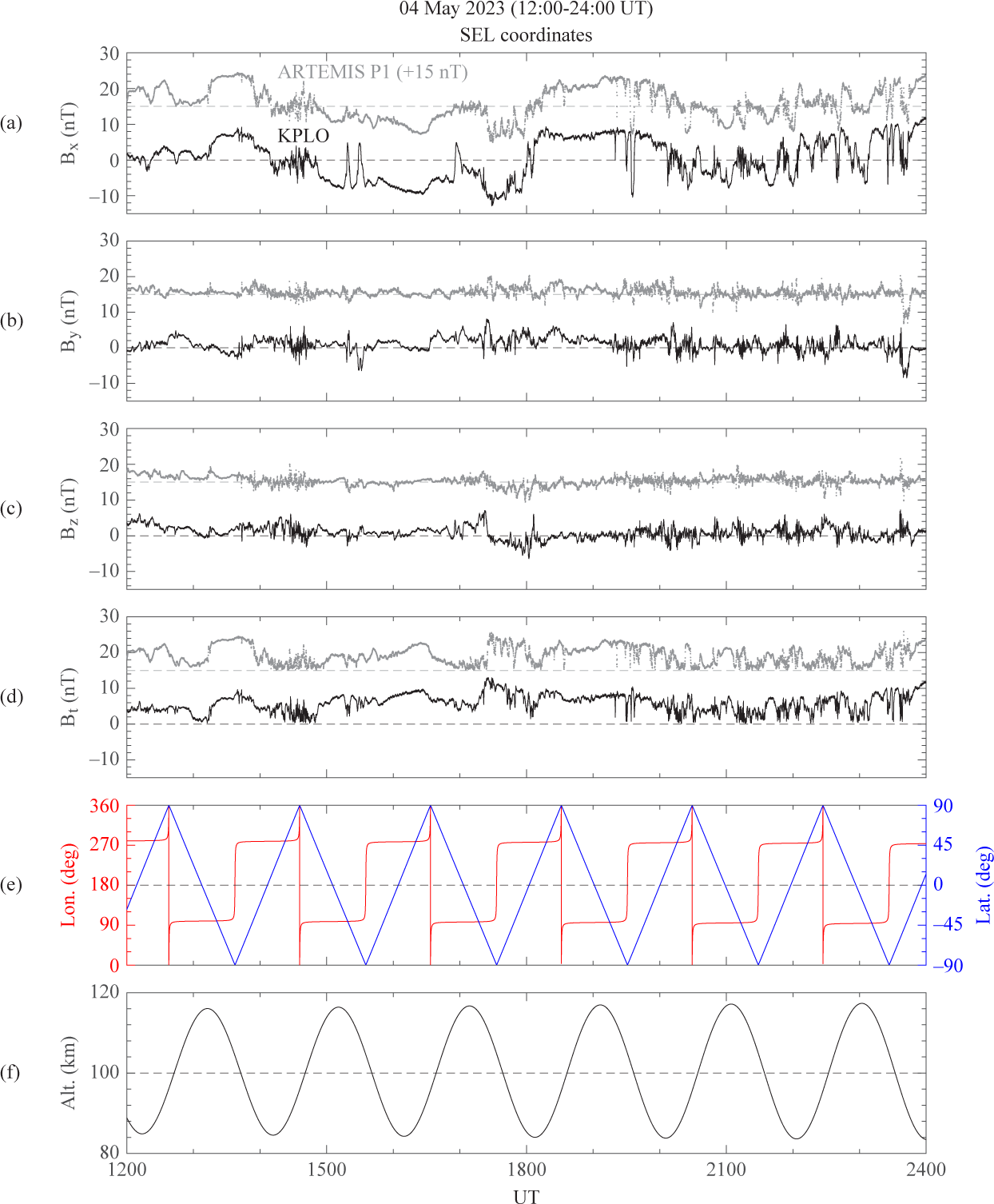
Fig. 15 shows the KPLO (blue) and ARTEMIS P1 (red) trajectories in the GSE equatorial plane and SSE equatorial plane during the 12:00–24:00 UT period on May 4, 2022, respectively, indicating that they are located within the magnetotail. Fig. 16(a)–16(d) represents magnetic field data from KMAG observed on May 4, 2023, along with ARTEMIS P1 data including a 15 nT offset. The positions of KPLO, which changes as it follows the Moon’s dawn-dusk orbital plane, are represented in the SEL coordinate system in Fig. 16(e) and 16(f). The spacecraft orientation changes constantly because of nadir pointing. Despite the complicated changes in the attitude of the spacecraft, KMAG at 100 km altitude exhibits similar features within 1–2 nT with respect to ARTEMIS P1. These results show the reliabilities of the KMAG in-flight calibration and KMAG data.
During lunar orbits, KPLO covers all orbital planes, from the dawn-dusk plane to the noon-midnight plane, every six months, maintaining a polar orbit. In particular, near the noon-midnight (LT 12–24 hr) orbital plane, the KPLO spends considerable time in the lunar wake region where the KPLO is within the solar wind. This is an area where the plasma effect of the solar wind is relatively small, and it helps in studying the magnetic field of the Moon. KPLO is located within a solar wind for much of the time, but when it is within the magnetotail (a short period of time per month periodically), a quiet background magnetic field environment is also good for measuring the lunar magnetic field.
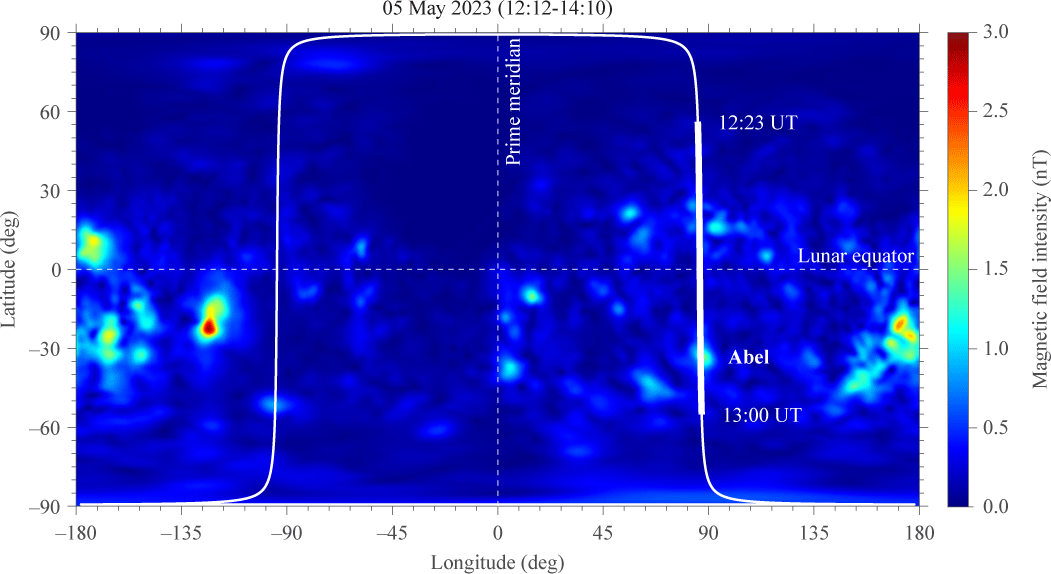
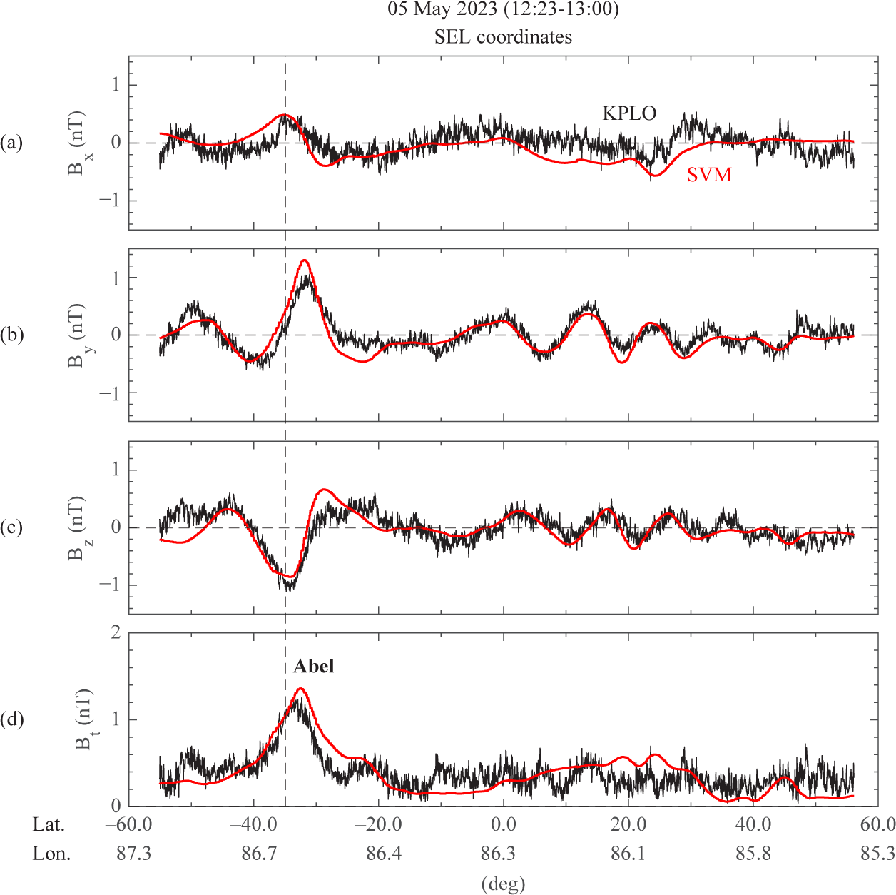
With diverse observation orbits, KMAG successfully observed lunar magnetic anomalies as well as solar wind events. Fig. 17 is a trajectory of an orbit in which KPLO passed over lunar magnetic anomalies, including Abel, which is located at 34.6 °S, 85.8 °E with a radius of 137.4 km, on May 5, 2023. KPLO is positioned in the magnetotail, one day apart from Fig. 15. The results obtained by KMAG between 12:23 UT and 13:00 UT are presented in Fig. 18, organized by latitude. The observations are compared with SVM’s 100 km observations based on previous observations by LP and Kaguya. KMAG observed about 0.5 nT of magnetic strength change in magnetic anomalies, similar to SVM.
6. SUMMARY AND DISCUSSION
KMAG operation has been stable for over one year. Using accumulated observations during the cruise orbit and lunar mission orbits, validation of KMAG data reliability has been achieved. Moreover, the data-processing pipeline and data calibration methods are established and updated more precisely. Furthermore, KMAG has successfully observed lunar magnetic fields such as lunar magnetic anomalies and lunar-induced magnetic fields, and solar wind events such as magnetic storms and magnetic clouds, in various environments, which we have been studying further.
However, the spacecraft’s magnetic interferences have not been fully eliminated because of the varied and complicated sources of spacecraft magnetic fields. In particular, the continuous maneuvering of the spacecraft during lunar orbits results in observations that include a significant amount of spacecraft-generated noise. Removing this is crucial for generating final research-grade data. Currently, two causes of the spacecraft noise field that have been investigated include the turning on and off of the valve-drive electronics (VDE) and the battery-charging current, with the possibility of more sources. The step-like and spike-like noise fields caused by the VDE can be removed using the PiCoG method (Magnes et al. 2020). However, the irregular and diverse noise field caused by battery discharging current is being researched, as is the removal of other factors. When these spacecraft field removal techniques are completed, more accurate offset determination and higher-quality data will be obtained.
Furthermore, complex thermal correction coefficients must be studied further on a case-by-case basis. Following a comprehensive temperature calibration, a revised version of the public data will be generated.
The KPLO mission has been extended by an additional three years beyond the initially planned mission duration, now reaching until 2025. During this extended mission period, if lunar magnetic field observations are possible in low orbits, it is expected that more meaningful and detailed studies of the lunar magnetic field, such as low-altitude lunar magnetic field mapping, can be conducted.
