1. INTRODUCTION
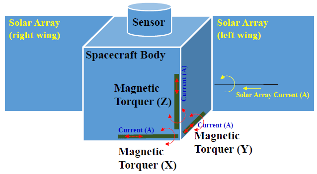
Recently, many satellites have been designed for various missions such as for Earth observation, communications, scientific missions, and technology demonstration. In these missions, the satellite requires sufficient electrical power to satisfy the power requirements in orbit. The electrical power required for satellite operation comes from a solarcell array using high power-conversion efficiency that considers the radiation effects (Shin et al. 2008, 2011, 2013). In the present work, we chose a 300-W solar-cell array using GaInP/GaAs/Ge solar cells to generate electrical power by photovoltaic conversion. This electrical power enables satellite-attitude control to precisely point the satellite to a target and maneuver the actuators into the target point using the magnetic-torque bars and reaction-wheel assemblies. The current around the magnetic-torque bars is crucial in generating precise momentum to maneuver the satellite. In addition, for a three-axis attitude-controlled satellite to maintain its direction, it must be able to adjust to the environmental torque that imparts angular momentum to the satellite (Herzl 2010). Magnetic torquers are also used for attitude control of small satellites such as CubeSats with low-Earth orbit (Kuyyakanont et al. 2018). During the satellite maneuver, electrical power is generated by the 300-W solar-cell array. The current from the 300-W solarcell array is crucial for more precise and accurate attitude control. In other words, the current through from the 300- W solar-cell array can affect the satellite maneuvering because it can create a magnetic dipole moment due to the electromagnetic field. The electromagnetic-field magnitude is determined by the current and area. Fig. 1 shows an example of the magnetic dipole moment and magnetic torque for attitude control using the solar-array current during operation in orbit. The current needs to be minimized to avoid its influence on the precise attitude control using the magnetic-torque bars. In the present study, we designed a 300-W solar cell array using GaInP/ GaAs/Ge solar cells by considering the magnetic dipole moment and presented optimal wire-routing paths to satisfy the requirements for a 0.25-A·m2 magnetic dipole moment of the 300-W solar-cell array.
2. DESIGN OF THE 300-W SOLAR-CELL ARRAY
Triple-junction GaAs solar cells have increasingly become popular in solar generators worldwide, whereas manufacturers are actively working on four to six junction cells to increase their conversion efficiency (De luca 2011). The 300-W solar-cell array has been designed considering the power requirement with a redundant string per array. The GaInP/GaAs/Ge cell technology is used in this array, which has 30% power-conversion efficiency. As soon as the GaInP/GaAs/Ge cell array is exposed to the sun, electrical power is generated. Thus, electric current flows through the conductors that are routed at the rear side of the substrate, creating a magnetic dipole moment generated by the photovoltaic current. Fig. 2 shows an entire electrical circuit that contains 352 solar cells (Shin et al. 2019).
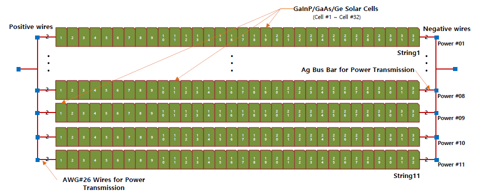
To comply with the system requirements, 11 strings were required for the current study. Therefore, we designed the electrical configuration, and the major parts are shown in Fig. 2, which shows that the individual strings contained 32 solar cells connected in series to generate a regulation voltage at maximum power during sunlight when in orbit (Shin et al. 2019). Each string was connected cell to cell, and all strings were electrically connected in parallel to provide the required current.
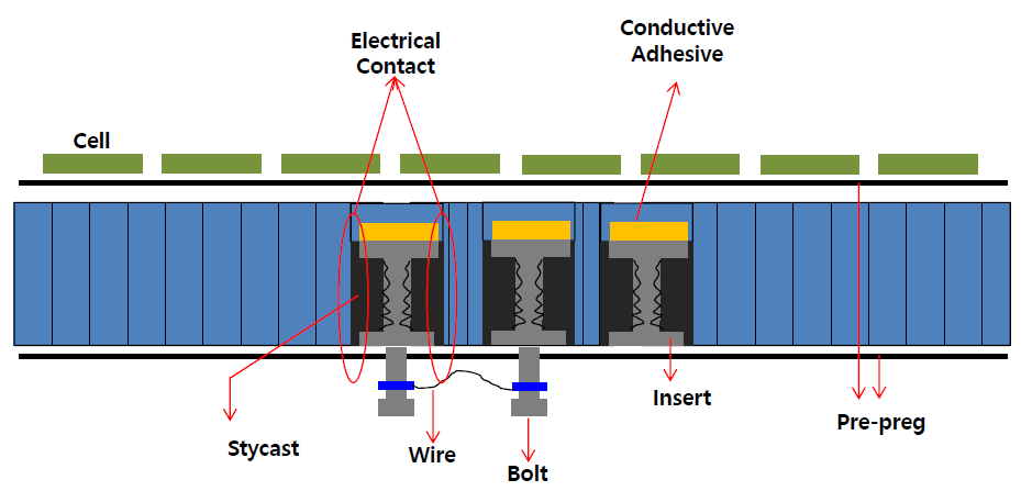
According to the electrical configuration and circuit design, we presented a mechanical design of the 300-W solar cell array that considered the strength and dynamics. In this study, 352 solar cells were fabricated and installed. The cell dimensions were 80 mm × 40 mm × 16 μm, and the overall size of the substrate was 1,200 mm × 1,350 mm to allow 352 solar cells on the substrate. The thickness of the substrate was 25 mm, which consisted of high- and lowdensity honeycomb cores. To minimize the magnetic dipole moment generated by the GaInP/GaAs/Ge solar cells, these solar cells were symmetrically installed at the left- and rightside parts of the substrate. However, the 11th string was installed at the center of the substrate to reduce the dipole moment, as shown in Fig. 3. Therefore, 352 solar cells were installed according to the dipole moment analysis. Fig. 3 shows the mechanical design and cell configuration.
3. ANALYSIS OF THE MAGNETIC DIPOLE MOMENT OF THE ARRAY
The magnetic dipole moment, which is generated by the string current and current loop in the substrate shown in Figs. 4 and 5, is expressed in Eq. (1). The time-varying dipole moment produced by the current loops in the solarcell array on board the satellite can be obtained from the integral representation of the magnetic dipole moment itself (Jeger 2017).
where I is the current flowing in the loop and A is the loop area of the solar-cell array. From the magnetic dipole moment definition in Eq. (1), a specific current-loop area is crucial for minimizing the torque created by the current that flows through the conductors. The magnetic dipole moments associated with the loop current that flows through each string are expressed as follows:
The 300-W solar cell array contained 11 strings to generate the required power of approximately 300 W at maximum current and voltage. The primary power was regulated using a regulation circuit to produce peak power at a given area. Thus, we considered the maximum power and minimum magnetic dipole moment for the actuators that regulated the amount of torque generated by the electrical circuits. In connection with the theory of magnetic dipole moment presented in Section 3.1, the individual strings contained the following electrical circuits and current loops.
Fig. 5 shows the entire strings of the 300-W solar-cell array. Each string consisted of a current loop related to its own current. The adjoining circuit and the other circuits were designed with the same structure to generate the same current and had the same current loops. Thus, the current in the first string in the left circuit was 0.5 A, and its effective current-loop area was approximately 0.00301 m2. We calculated the current-loop area as shown in Fig. 6, which consisted of several square blocks.
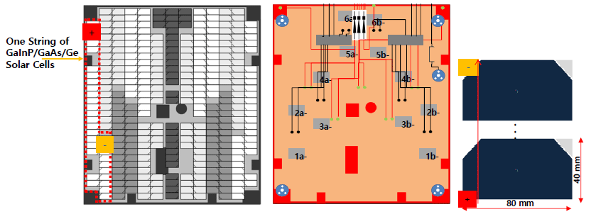
We calculated and obtained the effective current-loop area in the first string. We also calculated those of the other strings in the left array. All areas required for the calculation of the dipole moment were calculated. Table 1 lists a summary of the entire effective area.

|
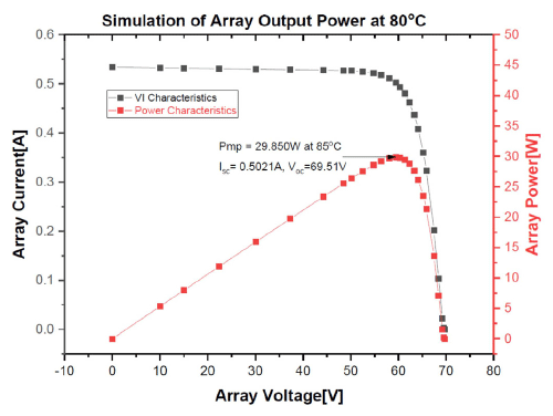
The 300-W solar-cell array contained 11 strings, and each string consisted of 32 solar cells in series. Thus, because every string had the same electrical circuit configuration, we calculated the loop current that flowed through a string conductor, as shown in Fig. 7 (Shin et al. 2019). The loop currents were calculated using the solar-cell formula or equation. Fig. 7 shows the existence of maximum current and voltage at the operating point. We calculated the effective loop area and loop current. According to the magnetic dipole moment expressed in Eq. (1), the total magnetic dipole moments of the 300-W solar cell array obtained from the two results are as follows:
In this solar-cell array, 11 strings were installed as the primary power source, including one redundant string for the mission requirements. All strings at the left and right wings have the same structure. Even if one string of the array fails, the system requirements can still be met. Table 2 lists the system analysis for a one-string failure in an array.
The list in Table 2 shows that the total magnetic dipole moment was 0.0567 A·m2 by considering the loop current and area, which satisfied the system requirements in terms of the effective loop area.
4. CONCLUSION
Power generation in space can only be achieved using sunlight. In this study, we designed a 300-W solar-cell array for a spacecraft power system and investigated the influence of magnetic dipole moment on the attitude actuators to determine if it was within a tolerable limit. The required magnetic dipole moment of the system for attitude control should not be more than 0.25 A·m2, as presented in Section 1. Because the system requires the maximum value, a smaller magnetic dipole moment can enable accurate position control during operation. The magnetic torquers were fabricated by looping a conductor in the shape of a coil. When a current flowed through the conductor, it generated control torque through the interaction with the geomagnetic field. The design of the magnetic torquers are straightforward, they are very cheap to produce, and are extremely reliable in operations. Moreover, they are lightweight and consume small electric power. Thus, magnetic torquers provide important advantages compared with other actuators (Miyata et al. 2009). In addition, the magnetic fields and solar microwaves are affected by the attitude control system (Sohn et al. 2012;Lee et al. 2017, 2018;Premkumar et al. 2019). Each string provided dipole moment values from 0.0530 to 0.060 A·m2. This study generated a 0.060-A·m2 magnetic dipole moment, which satisfied the system requirements of approximately 0.25 A·m2. According to the requirements, the 300-W solar-cell array was well designed and only minimally influenced the system. In addition, the electrical and mechanical designs of the proposed 300-W solar-cell array met the attitude-control requirements for minimizing the torque.


