1 INTRODUCTION
The Korea Pathfinder Lunar Orbiter (KPLO) project has a robotic lunar orbiting mission to collect high-resolution images of the lunar surface, and various scientific data. This data collection requires a stable satellite communication between the lunar orbiter and ground stations, and accurate tracking information. Accurate tracking information enables precise orbit determination (OD) of a spacecraft not only in the phasing loop transfer (maneuver burn) and lunar orbit injection phase, but also in the nominal mission operation phase (Bae et al. 2017). This OD accuracy affects attitude control accuracy, and accurate attitude control allows the payloads to capture data of the desired locations (Song et al. 2014). Except for a few contingency cases of the KPLO mission, ground stations exchange signals with the spacecraft and keep tracking the location of the spacecraft via the Doppler measurement and several ranging techniques similar to the approach used in many other lunar missions such as in the Chang’e 3 mission (Wenlin et al. 2017) and the Lunar Reconnaissance Orbiter (LRO) mission (Mazarico et al. 2012). In this paper, we focused on the ranging system and found the best ranging technique that can serve the KPLO mission successfully.
A ranging system utilizes radio frequency (RF) waveform propagation characteristics to determine the location of a spacecraft. The ranging signal being received at the ground stations, particularly the phase of the ranging signal, enables the calculation of the propagation time and the corresponding distance between the ground stations and the spacecraft. The performance of the range measurement varies depending on the structure of the ranging signal and the level of thermal noise. There are three commonly used criteria for range measurement performance. First is the measurement error of the time delay, which determines how accurate the ranging measurement is. Second is the probability of the ranging signal acquisition, while the third criterion is the measurement time that is required to measure the ranging signal. A longer measurement time renders higher accuracy and acquisition probability, but it also yields less location measurements in a given time. Thus, a system needs to be designed to meet the accuracy and acquisition probability requirements while maintaining a short measurement time.
Assuming that the thermal noise level is the same, the accuracy of a ranging system differs depending on the ranging technique used in the system. Radiometric ranging techniques such as tone ranging and pseudo-noise (PN) ranging have been the most widely used methods for tracking spacecrafts. Recently, satellite laser ranging (SLR) gained attention owing to its high precision (Lim et al. 2011; Choi et al. 2014). The Science and Technology Satellite (STSAT)-2C OD was also successfully launched and enhanced orbit predictions can be generated owing to its cm-level range precision (Kim et al. 2015). Although SLR is a subject of active research, owing to the technical assistance agreement (TAA) between Korea Aerospace Research Institute (KARI) and National Aeronautics and Space Administration (NASA), radiometric ranging techniques, which are supported by the Deep Space Network (DSN) and Near Earth Network (NEN), will be used for the KPLO mission. Since the radiometric ranging measurement accuracy for the DSN and NEN can be 1–2 m (JPL 2000), in this paper, it is demonstrated that the radiometric ranging is sufficiently accurate to satisfy the KPLO accuracy requirement.
Sequential ranging and PN ranging with T2B and T4B (weighted-voting balanced Tausworthe, voting v = 4) code, which are radiometric ranging techniques, can be supported as ranging methods. Thus, it is necessary to understand each ranging technique’s characteristics and find the best ranging technique for the KPLO mission. There have been several attempts to compare the performance of sequential ranging and PN ranging systems (Berner & Bryant 2002; Berner et al. 2007). It is known that PN ranging has the advantage of modifying its integration time in real time, while sequential ranging integration time is fixed by the code definition (Berner & Bryant 2002). This gives PN ranging more freedom to adjust its measurement performance in real time. A comparison between various PN codes was carried out in the work of Boscagli et al. 2007. The authors demonstrated that T4B is a valid choice for their mission considering the jitter requirement. However, an appropriate choice of a ranging method for the KPLO mission will be different since the requirements and specifications are different.
Aside from the ranging method being used in the system, the spacecraft communication system and the influence of ground stations on the measurement accuracy is also important. This naturally raises the problem of finding the end-to-end ranging accuracy. Most studies in the literature focused on the accuracy error due to thermal noise and the ranging methodology, while other error factors were often neglected (Ren et al. 2011; Jensen et al. 2013; Sheng 2014). In the CCSDS (2014), the ranging accuracy performance was addressed in terms of the received signal-to-noise ratio (SNR) regime, and the effect of the ranging clock frequency was evaluated. However, when other error sources exist, the decrease in the accuracy is not inversely proportional to the square root of the SNR. For instance, if the dominant factor of the end-to-end ranging accuracy is on the transponder, increasing the clock frequency or SNR will not significantly increase the accuracy.
In this paper, we first compared the accuracy of sequential ranging and PN ranging due to thermal noise. The endto- end ranging accuracy includes the ground sub-system instrumentation range error and the spacecraft’s communication RF circuitry error. The end-to-end ranging system accuracy analysis can help in the design of an overall efficient system specification. We further investigated the dominant factors of the ranging accuracy error and determined appropriate ranging parameters for the KPLO mission. Finally, we determined the optimal ranging method in terms of the measurement time that meets the requirements of accuracy and acquisition probability. Finding the ranging method with the shortest measurement time allows as many range measurements as possible, and this could help in conducting a successful mission.
The rest of this paper is organized as follows. The system model is described in Section 2, where we also analyzed the accuracy of the PN and sequential ranging methods. In Section 3, the end-to-end ranging accuracy and the optimal ranging methods suitable for the KPLO mission are presented. Finally, the conclusions are given in Section 4.
2 SYSTEM AND SIGNAL MODEL
The pulse-coded modulation/phase-shift keyed/phasemodulated (PCM/PSK/PM) modulation has been widely used in space communication systems and this modulation will also be utilized for the KPLO mission. This modulation process enables simultaneous transmission of telecommand/ telemetry and ranging signal. For instance, in uplink transmission, the non-return to zero (NRZ) telecommand data is PSK modulated, which is then PM modulated along with the ranging signal. Depending on the bandwidth constraint, a squarewave or sinewave subcarrier can be employed. Details of the characteristics of the modulation schemes are well addressed in the DSN handbook (JPL 2000). A sinewave subcarrier requires less spectrum bandwidth than a squarewave, which is suitable for the KPLO mission since it will be conducted in a bandwidth limited condition. Therefore, in this study, we considered a sinewave modulated signal. The uplink PCM/PSK/PM modulated signal, x(t), can be expressed as follows
where fc is the carrier frequency. The second phase term is the telemetry signal, where msTC is the modulation index, dTC(t) is the data, and fTC is the telecommand frequency. The third term represents the ranging signal, where mR is the modulation index, and fR is the range signal frequency. The ranging signal R(t) is configured in the ground station, and differs depending on the ranging method adopted in the system. For instance, R(t) is a constant one when sequential ranging is used. When PN ranging is used, R(t) is ±1, where its period is fR/2. We have are assumed that the ground stations that support the KPLO mission are capable of configuring sequential and PN ranging. This can possibly enhance the ranging performance by allowing flexibility in selecting a ranging method interchangeably.
In terms of the ranging method, the KPLO communication system will use transparent ranging. Transparent ranging does not require decoding and re-encoding of the ranging signal, which renders a simplified transponder design at the expense of uplink noise accumulation. In contrast, regenerative ranging eliminates the uplink noise term; thus, regenerative PN ranging is widely used in SNR limited Category B missions beyond Mars. Since the KPLO communication system will be operating in the Category A mission, transparent ranging is appropriate, and the following analysis is based on transparent ranging.
NASA’s DSN ranging system supports PN ranging in addition to the conventional sequential ranging, and it has been widely used in recent space missions. The PN code is a composite code generated from a logical operation of periodic binary component codes. Details of the code construction are well described in the CCSDS (2014). In this section, the ranging error due to thermal noise is addressed, while the composite end-to-end ranging error will be addressed in Section 3.1.
For a clock frequency f, the standard deviation of the ranging measurement error in rms meters, σT, is defined as follows (JPL 2000)
where the parameters represent the following
c: velocity of light
Ac: fractional loss of correlation amplitude due to frequency mismatch
R1: cross-correlation factor of the first component code
TPN: range measurement duration
PR/N0downlink SNR.
The cross-correlation factor of the first component code influences the accuracy, while the rest of the component codes (Rn, where n≠1) determine the acquisition probability, where they are defined by the code construction (Massey at el. 2007). The range measurement duration, TPN, affects both the accuracy and acquisition probability. Since the duration, TPN, can be adjusted in real-time during operation, it should be carefully analyzed to carry out appropriate adjustment during the mission. It should also be noted that PN ranging enables the measurement of all ranging components at once; thus, the integration time is the measurement time. Assuming that the measurement duration that satisfies the accuracy requirement is Tacc, and the duration that satisfies the acquisition probability requirement is Tacq, the measurement duration that satisfies both conditions should be the maximum of the two measure-ment time durations, as given below (JPL 2000)
Since the measurement duration takes the maximum of the required duration time, there exists a margin on one measurement criterion, and vice versa. For instance, if Tacq is greater than Tacc, there exists an accuracy margin corresponding to 10 log(TPN-Tacc) dB. Similarly, if Tacc is greater than Tacq, the system achieves higher acquisition probability corresponding to 10 log(TPN-Tacq) dB.
Sequential ranging signal structure is composed of a sequence of tone components, in which there are one major tone and n-1 number of minor tones. The major tone has the highest frequency and it determines the accuracy of ranging. The minor tones, which are often called ambiguity resolving tones, are followed by the major tone. They determine the acquisition probability and ranging ambiguity. Given a clock frequency f, the measurement error in rms meters, σT, can be expressed as follows (JPL 2000)
where T1 is the integration time of the major tone. We have assumed that all the parameters are defined the same as in PN ranging, except the integration time. The range measurement time of sequential ranging includes not only the integration time of the major tone, T1, but also the integration time of minor tones denoted as T2. Assuming that the total number of tones is n, the measurement time of sequential ranging Tseq is defined as follows (JPL 2000)
| Accuracy | Acquisition Probability | Clock Frequency |
|---|---|---|
| 1 m (rms) | 0.999 % | 500 kHz |
where n+1 number of one second dead times are located at the start of the tone, in between each tone, and at the end of the tone. Dead times are inserted as a margin for error, but they are not used in the signal integration. This is considered as the drawback of a sequential ranging system.
3 PERFORMANCE ANALYSIS AND COMPARISON
The system performance is limited by systematic errors and random errors. The former could be eliminated through calibration or compensated by adding offsets in the system. The latter, on the other hand, are usually unavoidable and influence the reliability of the measurement. We have assumed that systematic errors are predictable and controlled through calibration, while random errors are uncontrollable and influence the performance of ranging accuracy. In the end-to-end ranging system, the major random error sources are the ground stations, spacecraft communication system, and thermal noise. We have assumed that the random variables that can capture each of the random delay error sources are DG, DS, and DT, and their standard deviations are σG, σS, and σT, respectively.
The ground systems that support the KPLO mission will be NASA’s DSN and KDSA (Korea Deep Space Antenna). Since KDSA is still under development, we will consider the specifications of NASA’s DSN as a preliminary study. The ground system error sources include oscillator noise, group delay variation, and oscillator calibration. Details of the error sources and specifications are available in the DSN Handbook (JPL 2000).
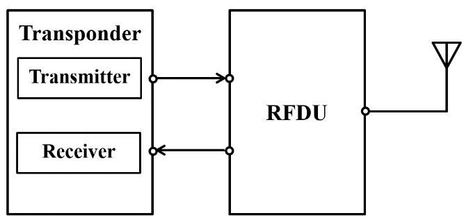
The simplified spacecraft communication system archi-tecture is illustrated in Fig. 1. The transponder is composed of the transmitter and the receiver, where modulation and demodulation are executed, respectively. In the radio fre-quency distribution unit (RFDU) block, there are diplexers that allow the transmitted and received signals to be conveyed on the same antenna. Furthermore, there are spurious rejection filters and switches that enable routing of the primary and secondary signal. The random delay error in the communication system is due to the signal routed from the RFDU and transponder backward and forward.
We have assumed that the total delay is represented by a random variable D, which is the summation of each delay error source as follows
Since the ground systems and the spacecraft communication system are designed independently, it is safe to assume that the random variables DG, DS, and DT are mutually independent. Thus, the total delay error variance is the summation of each variance, and its standard variation can be expressed as follows
In the remainder of this section, analytical results of the accuracy are presented in terms of the received SNR and the measurement time. In the analysis, we have assumed that the fractional loss Ac is 1, and we used the T2B code structure as PN ranging and compared its accuracy performance with sequential ranging. The outperformance of T2B over T4B in the KPLO mission is presented in Section 3.2. We used T to simplify the notation of integration time for PN (TPN) and sequential ranging (T1).
Fig. 2 shows the analytical results of the ranging measure-ment error due to thermal noise (σT). The figure shows that the accuracy increases as the clock frequency increases. For instance, if the clock frequency is doubled, the accuracy is reduced by half. The figure also shows that the sequential ranging accuracy is slightly higher than that of PN ranging. This is an expected result since the PN ranging peak power is spread out beside the clock frequency; thus, PN ranging has lower peak power than sequential ranging. However, the difference decreases as the SNR increases, and since KPLO will mostly operate in a high SNR regime, it is safe to assume that the difference is negligible. Note that the integration time of PN ranging is the measurement time, and PN ranging requires less measurement time for each range measurement than sequential ranging. Thus, PN ranging has more margin to increase its measurement time and accuracy than sequential ranging.
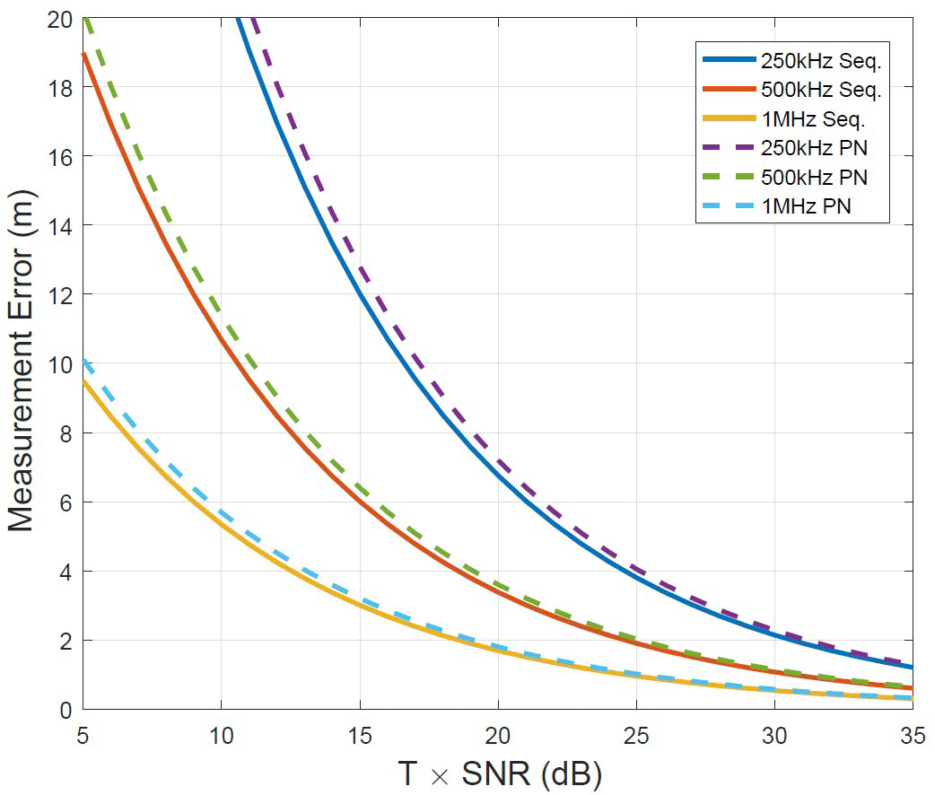
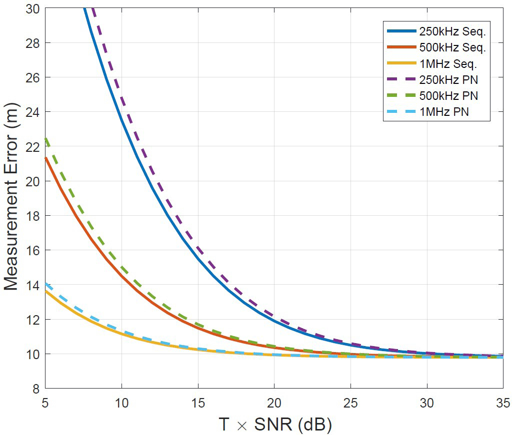
Fig. 3 shows the end-to-end range measurement error. The figure shows that in the KPLO communication system, the estimated standard deviation of the time delay is approxi-mately 64 ns. The corresponding one-way distance error variation, σS, is 9.6 m. In terms of the ground station error, we used the specification defined in module 203 of the DSN Handbook (JPL 2000), where the distance error variation, σG, is 1.89 m. The figure shows the same overall tendency depicted in Fig. 2. However, the major difference is that the accuracy does not increase as much as in Fig. 2 in the high SNR regime. This is because the dominant error source in the high SNR regime is from the spacecraft. Thus, the accuracy improvement by SNR is insignificant in the high SNR regime. Similarly, accuracy improvement by clock frequency is also negligible since the accuracy error due to thermal noise is much smaller than the error from the spacecraft. This finding can be useful in selecting the ranging clock frequency for the KPLO mission. A typical value for the ranging clock frequency is 1 MHz; however, the KPLO transponder under development only operates on 500 kHz ranging clock frequency and it requires additional efforts and resources to have the capability to handle 1 MHz ranging tone. These results show that 1 MHz clock frequency does not render accuracy improvement considering the current end-to-end system specifications.
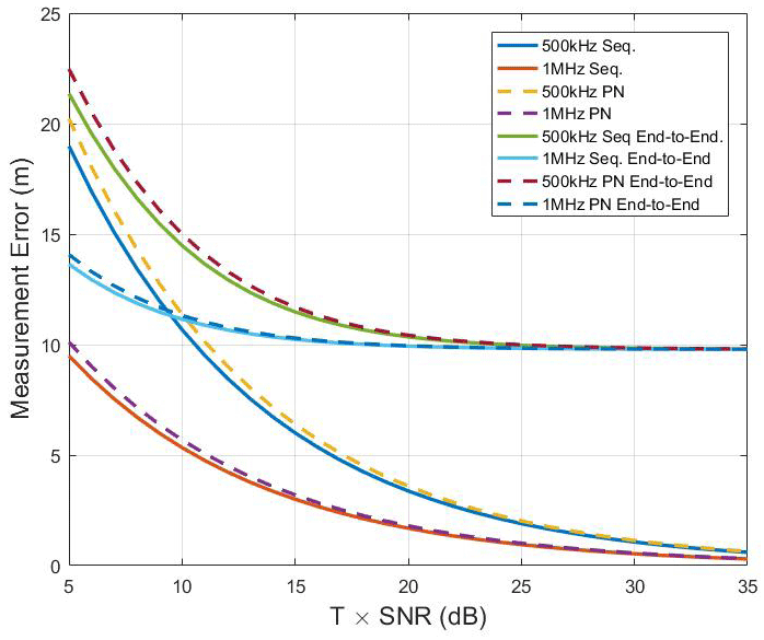
In Fig. 4, the ranging measurement error due to thermal noise and the end-to-end error are compared for clock frequencies of 500 kHz and 1 MHz. The figure demonstrates that increasing the clock frequency from 500 kHz to 1 MHz results in up to 1 m accuracy improvement for the KPLO communication operation region, which is approximately 25 to 30 dB SNR. However, since the end-to-end error incorporates the KPLO communication system error, which is the major error source, the benefit from increasing the clock frequency is meaningless since the error due to thermal noise is much smaller than the one caused by the KPLO communication system (σT ≪ σS)
This section presents a comparison of the performance of the ranging techniques in terms of the measurement time. The ranging techniques considered were sequential ranging, T2B code, and T4B code ranging, which are all CCSDS defined formats and are available for the KPLO mission. Table 1 presents the ranging requirements and specifications, where the values have been practically selected, but could differ from the actual values used in the KPLO mission. The accuracy requirement of 1 m (rms) is for the error due to thermal noise only, and we omitted other error sources from the specification since thermal noise is the only error source that is manageable by adjusting parameters such as the transmit power and the measurement time.
Fig. 5 plots the duration times of each ranging measurement in terms of the received SNR. The figure shows that in the low SNR regime where the SNR is below 17.5 dB, sequential ranging has the shortest measurement time, while in the high SNR regime where the SNR is above 17.5 dB, the T2B code has the shortest measurement time. Although the T4B code out performed sequential ranging above SNR of 22 dB, its measurement time is greater than that of T2B in the SNR span considered in this analysis. The figure also demonstrates that selecting the best ranging technique can help in saving power. For instance, sequential ranging required 25 dB received SNR and 25 sec measurement time to achieve an accuracy of 1 m, but T2B requires only approximately 20 dB received SNR with the same measurement time of 25 sec, which renders approximately 5 dB gain over sequential ranging. This received SNR gain allows the possibility to increase the data rate or reduce the error rate of the telecommand, and this can be achieved by increasing the telecommand modulation index mTC in Eq. (1).
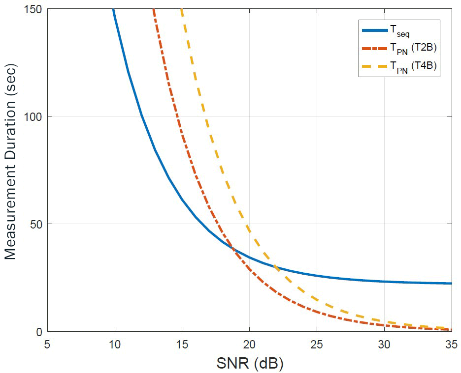
Fig. 6 shows a detailed analysis of the measurement time. In general, the T4B code provides a better accuracy than the T2B code, whereas the T2B code has better acquisition probability than the T4B code. It can be observed in Fig. 6 that Tacc of T4B is shorter than that of T2B, and Tacq of T2B is shorter than that of T4B. The figure also reveals that when the accuracy requirement is relaxed, such that Tacc of T2B is shorter than Tacq of T4B, T2B performs better than T4B.
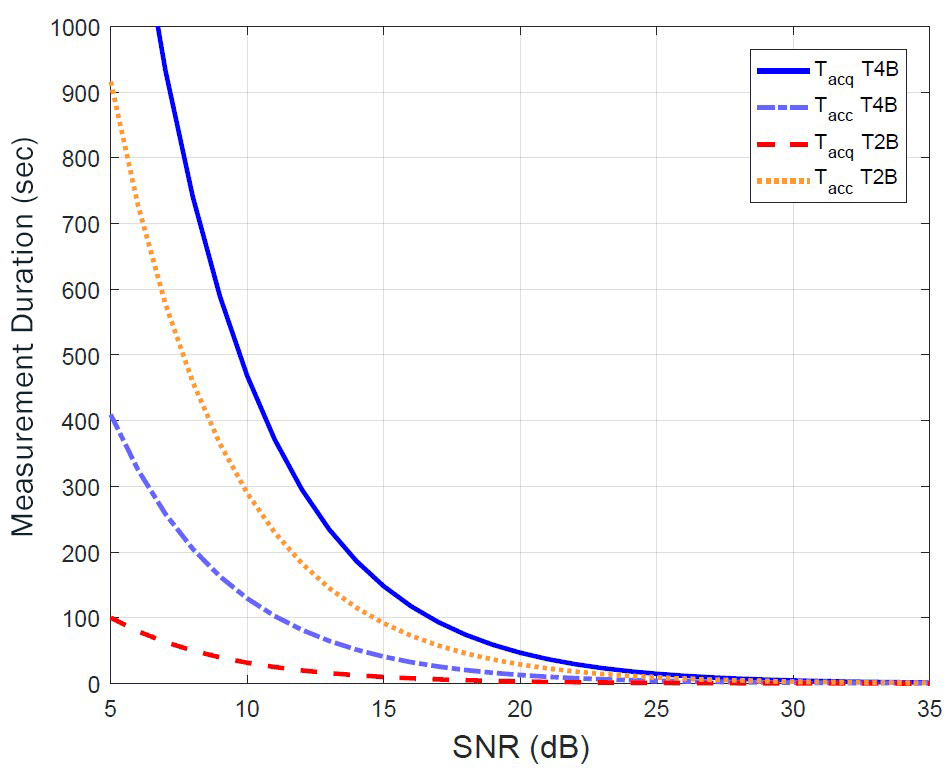
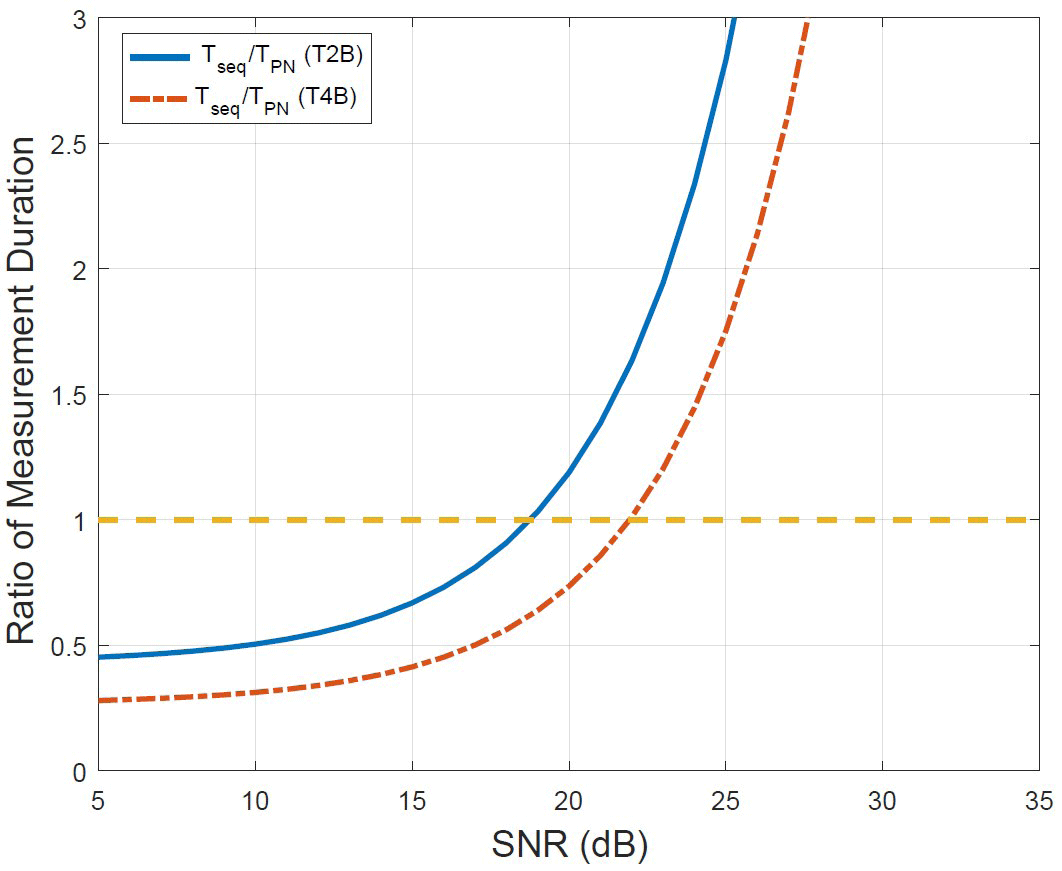
Fig. 7 shows another comparison of results under the same constraints as in Fig. 6. The figure shows the ratio of the measurement time of sequential ranging over PN ranging. This result also demonstrates that sequential ranging had the best performance in the low SNR regime while T2B had the best performance in the high SNR regime. A notable analytical result is that the ratio of the measurement time exponentially increases as the received SNR increases.
4 CONCLUSIONS
In this paper, the analytical results of the end-to-end ranging measurement performance for the KPLO mission were presented. Error sources such as in the ground stations and spacecraft communication system are often neglected when it comes to selecting a ranging technique and finding the corresponding ranging parameters. However, when these error sources are incorporated, results presented in this paper demonstrate that the selection of a ranging technique and its clock frequency (T2B with 500 kHz clock frequency) gives a different performance from the ones that solely considered the thermal noise error (T4B with 1 MHz clock frequency). We also showed that this is because the dominant error source is independent of the error due to thermal noise.
We further analyzed and compared ranging techniques using the criterion of measurement duration, while the accuracy requirements and specifications were met. We found that the ranging technique with the shortest measurement duration differ in the received SNR, i.e., the best ranging technique differ in the received SNR. Given the KPLO require-ments, it was shown that the performance threshold between sequential and T2B PN ranging technique was a received SNR of 17.5 dB. Considering the KPLO operating received SNR region of 25–30 dB, we found that the T2B code performed better than the T4B code. We further demonstrated that by selecting the best ranging technique, there was a power gain of 5 dB for the received SNR of 25 dB. This is because the T4B code does not take advantage of the short measurement duration required to achieve accuracy in the KPLO mission. These findings reveal that PN ranging with the T2B code is the best ranging technique among the ranging techniques available for the KPLO mission.